


SOFTWARE OVERVIEW
P485 MODBUS TO PROFIBUS CONVERTER – USER GUIDE 4–13
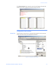
Modbus network configuration
OVERVIEW When controlling a Modbus sub-network with the P485 it is important to understand
functions during starting up. If the P485 starts scanning nodes on the sub-network, before
data is received from the fieldbus control system (fieldbus master), values of ‘00’ may be
transmitted to the nodes before data is updated the first time from the fieldbus.
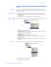
See Input/output data during startup on page 8–4 for information on how to block
transactions until valid data is received.
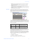
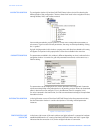
SERIAL INTERFACE
SETTINGS
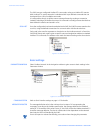
To be able to communicate on the Modbus network, various communication settings
needs to be configured. To gain access to these settings, select ‘Modbus Network’ in the
Navigation window.
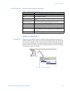
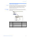
Parameter Description Range
Bit rate Selects the bit rate. 1200 to 57600
Data bits Selects the number of data bits. 7, 8
Parity Selects the parity. None, Odd, Even
Physical standard Selects the physical standard. This setting
activates the corresponding signals on the subnet
connector.
RS232, RS422, RS485
Start bits Only one start bit is supported. 1
Stop bits Either one or two stop bits can be selected. 1, 2