


P485 MODBUS TO PROFIBUS CONVERTER – USER GUIDE 8–1
GE Consumer & Industrial
P485 Modbus to Profibus
Converter
Chapter 8: Advanced functions
Advanced functions
Control and status registers
DESCRIPTION The control/status registers forms an interface for exchanging information between the
fieldbus control system and the P485.
The main purpose of these registers is to report Modbus network related problems to the
fieldbus control system. This interface is also used to ensure that only valid data is going
out on the sub-network and that valid data is reported back to the fieldbus control system.
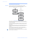
See 8-4 “Input/output data during startup”.
Using these registers, it is also possible for the fieldbus control system to instruct the P485
to enable / disable specified nodes.
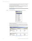
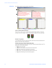
By default, these registers are located in the internal memory buffer at 0x000 - 0x001
(Status Register) and 0x200 - 0x201 (Control Register), however they can be disabled using
EnerVista P485/D485 Setup, see Modbus network configuration on page 4–13. Disabling
these registers will release the 2 reserved bytes in the internal memory buffer, however, the
Status and Control functionality will not be available.
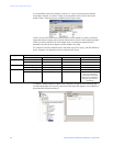
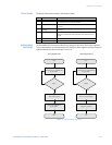
The handshaking procedure described on page 8-3 must be followed for all changes to
these registers
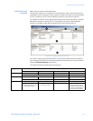
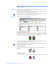
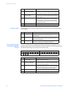
CONTROL REGISTER
(PROFIBUS CONTROL
SYSTEM TO P485)
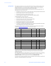
Bytes 0 and 1 of the control register are shown below.
Byte 0 (Offset 0x200) Byte 1 (Offset 0x201)
15 14 13 12 11 10 9 8 7 6 5 4 3 2 1 0
- - - Control Code Data