


2–4 P485 MODBUS TO PROFIBUS CONVERTER – USER GUIDE
INSTALLATION
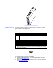
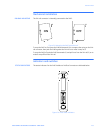
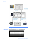
Figure 2-5: Configuration cable (PC end)
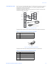
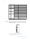
MODBUS CONNECTOR The Modbus connector is indicated as C in Figure 2-1: P485 electrical connections on page
2–2. This connector is used to connect the P485 to the serial network. Based on the
configuration selected in the EnerVista P485/D485 Setup software, the corresponding
signals are activated.
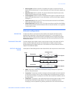
Figure 2-6: Modbus connector
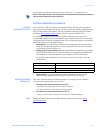
POWER CONNECTOR The power connector is indicated as D in Figure 2-1: P485 electrical connections on page
2–2. Use this connector to apply power to the P485.
Pin 1: +24 V DC;
Pin 2: ground
Use 60/75 or 75°C copper (CU) wire only. The terminal tightening torque must be between
5 to 7 lbs-in (0.5 to 0.8 nm).
Figure 2-7: Power connector
51
69
(female)
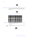
Table 2–4: Modbus connector pin assignments
Pin Description RS232 RS422 RS485
1 +5 V output (50 mA max)
2 RS232 Rx 3
3 RS232 Tx 3
4 Not connected
5 Ground 333
6 RS422 Rx + 3
7 RS422 Rx – 3
8 RS485 + / RS422 Tx+ 33
9 RS485 – / RS422 Tx– 33
51
69
(female)
NOTE
12