


P485 MODBUS TO PROFIBUS CONVERTER – USER GUIDE i
GE Consumer & Industrial
P485 Modbus to Profibus
Converter
Table of contents
INTRODUCTION Getting started........................................................................................................1–1
Inspecting the package and product.................................................................................................1–1
Contact information...................................................................................................................................1–1
Document conventions..........................................................................................1–2
Description .....................................................................................................................................................1–2
Glossary...........................................................................................................................................................1–2
About the P485 Modbus to Profibus Converter.................................................1–3
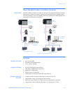
Application......................................................................................................................................................1–3
Features....................................................................................................................1–3
General features..........................................................................................................................................1–3
Modbus network..........................................................................................................................................1–3
Fieldbus interface features.....................................................................................................................1–3
Ordering ...................................................................................................................1–4
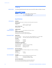
Order codes....................................................................................................................................................1–4
Specifications ..........................................................................................................1–4
Mechanical.....................................................................................................................................................1–4
Electrical characteristics..........................................................................................................................1–4
Communications .........................................................................................................................................1–4
Environmental...............................................................................................................................................1–4
EMC compliance ..........................................................................................................................................1–4
INSTALLATION Quick install .............................................................................................................2–1
Procedure........................................................................................................................................................2–1
Electrical installation .............................................................................................2–1
Overview..........................................................................................................................................................2–1
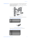
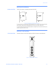
Profibus connector .....................................................................................................................................2–2
Configuration cable....................................................................................................................................2–3
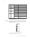
Modbus connector......................................................................................................................................2–4
Power connector .........................................................................................................................................2–4
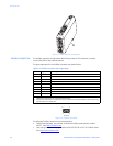
Mechanical installation .........................................................................................2–5
DIN-rail mounting........................................................................................................................................2–5
Indicators and switches ........................................................................................2–5
Status indicators..........................................................................................................................................2–5
Configuration switches.............................................................................................................................2–6