


COMMUNICATION MODEL
P485 MODBUS TO PROFIBUS CONVERTER – USER GUIDE 5–3
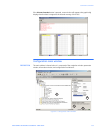
Nodes
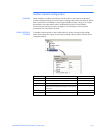
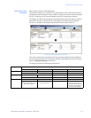
DESCRIPTION A node in the EnerVista P485/D485 Setup software represents a device on the Modbus
sub-network. In it’s simplest form, a Node contains of a single transaction, that consists of
a Query and a Response.
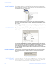
NODE PARAMETERS To gain access to these parameters, select the desired node in the navigation window.
• Slave address: This setting shall be set to match the Modbus address setting of the
destination device.
• Name: Node Name. This name will appear in the navigation window.
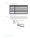
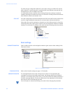
MODBUS NETWORK
MENU
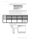
Right-click “Modbus Network” in the Navigation window to gain access to these functions.
Figure 5-4: Modbus network menu
• Paste: Paste a node from the clipboard.
• Modbus Network Monitor: Launches the Modbus network monitor. Refer to Modbus
network monitor on page 7–1 for details.
• Add Node: Adds a node to the scanlist.
• Add Broadcaster: Adds a broadcaster node to the scanlist.
• Load Node: Loads a node previously saved using “Save Node” from the Node menu
(see details below).
• Modbus Network Status: Displays status/diagnostic information about the Modbus
network.
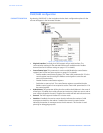
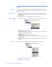
NODE MENU Right-click on a node in the Navigation window to gain access to these functions.
Figure 5-5: Node menu
• Cut: Cuts a node to the clipboard.
• Copy: Copies a node to the clipboard.