


Installation and Setup
3A0415D 7
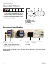
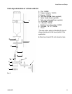
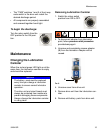
Circuit Board Settings
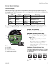
Function Display
Red and green LED’s (Light Emitting Diodes) are on the circuit board and visible through the
transparent cover. The following signals about operating conditions/malfunctions are displayed by
these LED’s for the user:
There is a 4-way code switch on the circuit board. TIME switches 1 + 2 are used to set the dis-
charge period. VOL switches 3 + 4 are used to set the size of the lubrication canister.
ALED Red
BLED Green
C 4-way code switch
D battery pack contacts
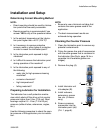
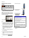
Setting Dip Switches
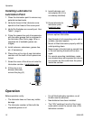
1. Unscrew and remove the cover.
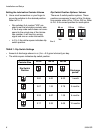
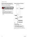
Setting the Discharge Period (TIME)
2. Use a small screwdriver or your finger to
move dip switches to the desired position.
Refer to FIG. 4.
• The discharge period is pre-set to 6
months.
• Dip switches 1+2 marked “TIME” are
used to set the discharge period.
• In FIG. 4 the white square indicates dip
switch position.
Dip Switch Position Options: Time
There are 4 switch position options: 1, 3, 6 and
12 months. Refer to FIG. 4 for correct position
for each option.
LED Signal Signal Time Meaning
Green Blinking
Every 15
seconds
System functions OK
Red Blinking
Every 8
seconds
Malfunction / error
Green
and Red
Blinking
Every 3
seconds
Lubricator unit is empty.
Change canister.
Red Steady signal Steady Unit is discharging lubricant.
FIG. 3
C
A
B
D
12 34
FIG. 4
12
6 Months
Time
12
12 Months
Time
12
1 Months
Time
12
3 Months
Time