


2–4 System Hardware Description
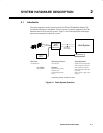
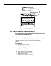
2.4 Scanner/Host Communication
The RS–232 communications interface of the 3700 is used for entering configuration
commands from a PC or host instrument for specific application requirements. The
communications I/O port also sends decoded bar code data to the host.
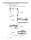
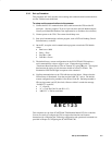
2.4.1 Communications Port
The communications port connector for the 3700 is an 8–pin female modular socket for
interfacing to the host system or other communications device. Communications
between the host system and the 3700 occur using an Asynchronous ASCII protocol.
Refer to Appendix B for a complete description of pin assignments of the RS–232
communications port.
Caution: Do not use a host communications cable with more wires connected than are
required for the application. Damage to equipment within the system may result if
the communications connection is improperly wired.
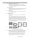
2.4.2 Asynchronous Serial ASCII Interface
The Asynchronous serial ASCII Interface operates in Full Duplex Mode. Software
configuration parameters (see Chapter 4) control Baud Rate, Parity, Data Bits, Stop Bits,
Xon/Xoff, ACK/NAK, RTS/CTS, and Pre/Postambles.
Baud rate is a means of expressing data transmission speed, where “baud” equals the
number of signal events per second (roughly equivalent to bits per second). Parity is a
means of checking character bit patterns for validity by confirming if they contain an
Even or Odd number of “1”s. The communications port can be configured to operate at
baud rates of 600, 1200, 2400, 4800, 9600, 19200, and 38400, with even, odd, or no
parity.
Data bits refers to the number of bits used to encode each ASCII character in a data
message. Stop bits refers to the number of stop bits appended to each character. The
communications port can be configured to send 7 or 8 data bits, with 1 or 2 stop bits.
Note: For proper operation the 3700 must be configured for the same baud rate, parity, number
of data bits, and number of stop bits as the connected RS–232 host device.
Xon/Xoff are control characters that refer to ASCII characters “DC1” and “DC3,”
respectively. If enabled, Xon/Xoff is a method to control data flow in the following
manner. Whenever its buffers approaches full, the device receiving communications data
sends an “Xoff” to stop data transmission. The transmitting device stops data
transmission. When its buffer approaches empty, the receiving device sends “Xon” and
the transmitting device starts sending data again. The receiving device refers to the host
instrument. Likewise, the transmitting device refers to the 3700.
Note: The SCANTEAM 3700 will respond to XON and XOFF characters from the host, but will
not send these characters.