


Using Authorized IP Managers
Building IP Masks
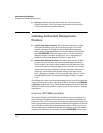
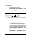
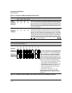
Figure 11-5. Analysis of IP Mask for Multiple-Station Entries
1st
Octet
2nd
Octet
3rd
Octet
4th
Octet
Manager-Level or Operator-Level Device Access
IP Mask 255 255 255 0 The “255” in the first three octets of the mask specify that only the exact
Authorized 10 28 227 125
value in the octet of the corresponding IP address is allowed. However,
Manager IP
the zero (0) in the 4th octet of the mask allows any value between 0 and
255 in that octet of the corresponding IP address. This mask allows switch
access to any device having an IP address of 10.28.227.xxx, where xxx is
any value from 0 to 255.
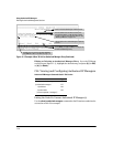
IP Mask 255 255 255 249 In this example (figure 11-6, below), the IP mask allows a group of up to
Authorized 10 28 227 125-
4 management stations to access the switch. This is useful if the only
devices in the IP address group allowed by the mask are management
IP Address-
stations. The “249” in the 4th octet means that bits 0 and 3 - 7 of the 4th
octet are fixed. Conversely, bits 1 and 2 of the 4th octet are variable. Any
value that matches the authorized IP address settings for the fixed bits is
allowed for the purposes of IP management station access to the switch.
Thus, any management station having an IP address of 10.28.227.
121
, 123,
125
, or 127 can access the switch.
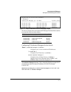
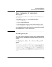
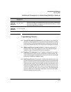
4th Octet of IP Mask:
4th Octet of Authorized IP Address:
249
5
Bit Numbers Bit Bit Bit Bit Bit Bit Bit Bit
7 6 5 4 3 2 1 0
Bit Values 128 64 32 16 8 4 2 1
4th Octet of
IP Mask (249)
4th Octet of
IP Authorized
Address (125)
Bits 1 and 2 in the mask are “off”, and bits 0 and 3
- 7 are “on”, creating a value of 249 in the 4th octet.
Where a mask bit is “on”, the corresponding bit
setting in the address of a potentially authorized
station must match the IP Authorized Address
setting for that same bit. Where a mask bit is “off”
the corresponding bit setting in the address can be
either “on” or “off”. In this example, in order for a
station to be authorized to access the switch:
•- The first three octets of the station’s IP address
must match the Authorized IP Address.
•- Bit 0 and Bits 3 through 6 of the 4th octet in the
station’s address must be “on” (value = 1).
•- Bit 7 of the 4th octet in the station’s address
must be “off” (value = 0).
• Bits 1 and 2 can be either “on” or “off”.
This means that stations with the IP address
13.28.227.X (where X is 121, 123, 125, or 127) are
authorized.
Figure 11-6. Example of How the Bitmap in the IP Mask Defines Authorized Manager Addresses
11-12