


Removal and replacement procedures 43
The following table lists some, but not all, possible configurations. For best performance, HP recommends
dual-bank interleaved mode configurations.
Slot 1A Slot 2B Slot 3A Slot 4B Total memory Mode
512 MB — — — 512 MB Single-bank
512 MB — 512 MB — 1 GB Dual-bank interleaved
1 GB — — — 1 GB Single-bank
1 GB — 1 GB — 2 GB Dual-bank interleaved
1 GB 1 GB 1 GB 1 GB 4 GB Dual-bank interleaved
Interleaving and non-interleaving memory configuration
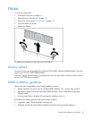
The server supports interleaving and non-interleaving memory configurations. Interleaving memory
increases bandwidth by enabling simultaneous access to multiple blocks of data. For example, to overlap
read-writes, the server divides the system memory between pairs of DIMMs, and then writes to and reads
from each DIMM concurrently. For an interleaving configuration, always install identical DIMMs in pairs.
For a non-interleaving configuration, install a single DIMM in slot 1 only.
Power supply
To remove the component:
1. Power down the server (on page 26).
2. Remove the server from the rack (on page 26).
3. Remove the access panel ("Access panel" on page 27).
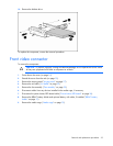
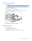
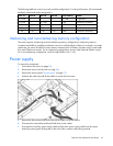
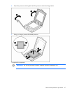
4. Unfasten the cable clip and lift the cables to access the front screw.
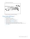
5. Remove the three screws that secure the power supply unit to the chassis.
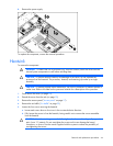
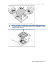
6. Disconnect the removable media and hard drive power cables.
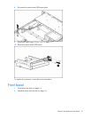
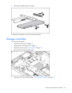
7. Disconnect the auxiliary power supply cable and the main power supply cable from the system
board by pressing each locking tab on the side of the connector and pulling upwards.