


iv
Table of Figures
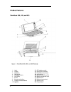
Figure 1 - OmniBook 300, 425, and 430 Features .......................................................................2
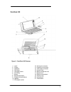
Figure 2 - OmniBook 530 Features..............................................................................................3
Figure 3 - Serial Loop Back Connector ......................................................................................11
Figure 4 - Parallel Loop Back Connector ...................................................................................11
Figure 5 - OmniBook Memory Modules .....................................................................................48
Figure 6 - Removing the Memory Module..................................................................................49
Figure 7 - Removing Card Slot Tray..........................................................................................51
Figure 8 - Removing the Mouse ................................................................................................52
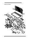
Figure 9 - Outer Bottom Case Components...............................................................................54
Figure 10 - Backplane Standoffs................................................................................................55
Figure 11 - Bottom Case Tabs...................................................................................................55
Figure 12 - Bottom Case Prying Locations.................................................................................56
Figure 13 - I/O Port Prying Location ..........................................................................................56
Figure 14 - Disconnecting Display Cable ...................................................................................57
Figure 15 - Keyboard Flex Cables .............................................................................................58
Figure 16 - Display Grounding Eyelets.......................................................................................58
Figure 17 - Display Cable Probe Position ..................................................................................60
Figure 18 - Reconnecting Display Cable....................................................................................60
Figure 19 - I/O Port Eyelets (all present)....................................................................................61
Figure 20 - I/O Port Eyelets (two matched sets).........................................................................61
Figure 21 - I/O Port Eyelets (only one matched set)...................................................................61
Figure 22 - I/O Port Eyelets (no eyelet in position one)..............................................................61
Figure 23 - Logic Board PCA Removal......................................................................................63
Figure 24 - Paw Carrier Removal ..............................................................................................65