


63
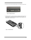
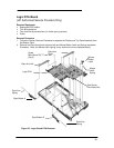
Logic PCA Board
(HP Authorized Service Providers Only)
Required Equipment
• Appropriate ESD station
• Torx #6 screwdriver
• Two small flat tip screwdrivers (or similar prying devices)
• Probe
Removal Procedure
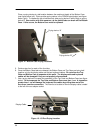
1. Follow the Display Removal Procedure to separate the Display and Top Case Assembly from
the Bottom Case.
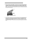
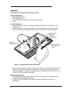
2. Remove the Eject Arms (both right and left) and Mouse Button Latch and Spring (see below
illustration). Note, the Mouse Latch Spring is very small and can be misplaced easily.
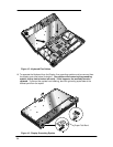
Figure 23 - Logic Board PCA Removal
Mouse
Button
Latch
Eject Arm Left
Eject Arm
Right
Eject Button A
Eject Button B
Eject Arm
Spring
Eject Arm
Spring
Screw
M2x4.6mm(T6)
(Qty 5)
Mouse
Latch
Spring
Paw Carrier
Flex Cable Slot
Logic PCA