


i.
Speaker (see
Speaker on page 96)
j. Audio/ExpressCard assembly (see
Audio/ExpressCard assembly on page 97)
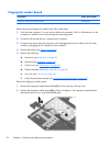
When replacing the system board, be sure that the following components are removed from the
defective system board and installed on the replacement system board:
●
Memory module (see
Expansion memory module on page 62 and Primary memory module
on page 67)
●
WWAN module (see
WWAN module on page 63)
●
Modem module (see
Modem module on page 69)
●
WLAN module (see
WLAN module on page 70)
●
RTC battery (see
RTC battery on page 73)
●
Fan (see
Fan on page 77)
●
Heat sink (see
Heat sink on page 78)
●
Processor (see
Processor on page 83)
Remove the system board:
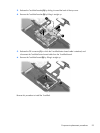
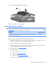
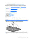
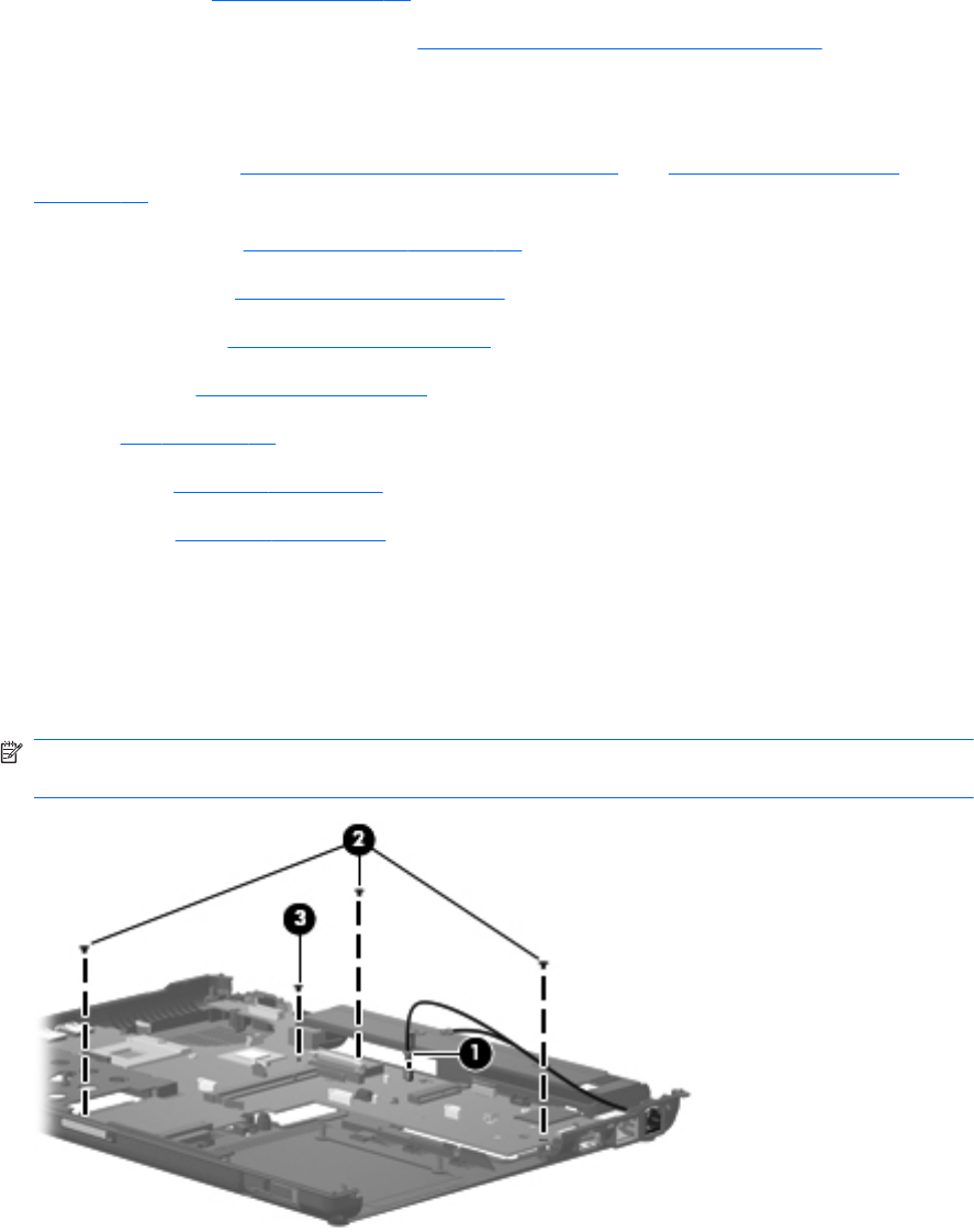
1. Disconnect the modem module cable (1) from the system board.
2. Remove the three Phillips PM2.5×4.0 screws (2) that secure the system board to the base
enclosure.
NOTE: Computer models equipped with UMA graphics subsystem memory will have a fourth
Phillips PM2.5×4.0 screw (3) securing the system board to the base enclosure.
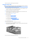
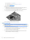
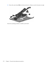
3. Use the optical drive connector (1) to lift the right edge of the system board (2) until it rests at an
angle.
Component replacement procedures
101