


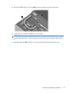
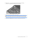
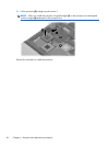
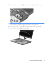
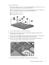
9.
Remove the wireless antenna cables (2) from the clips and routing channels built into the top
cover.
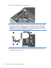
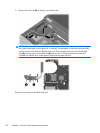
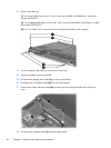
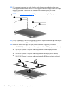
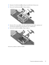
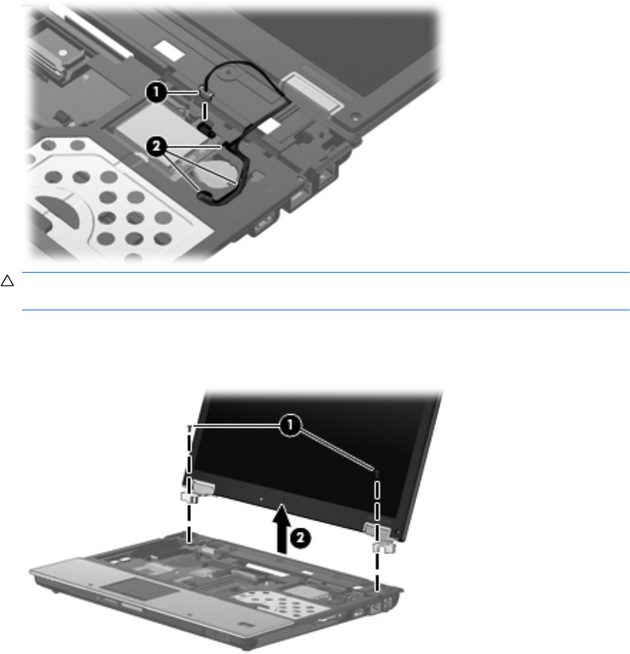
CAUTION: The display assembly will be unsupported when the following screws are removed.
To prevent damage to the display assembly, support it before removing the screws.
10. Remove the two T8M2.5×7.0 screws (1) that secure the display assembly to the computer.
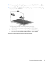
11. Remove the display assembly (2) by lifting it straight up.
Component replacement procedures
87