


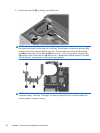
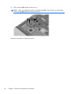
12.
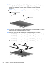
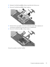
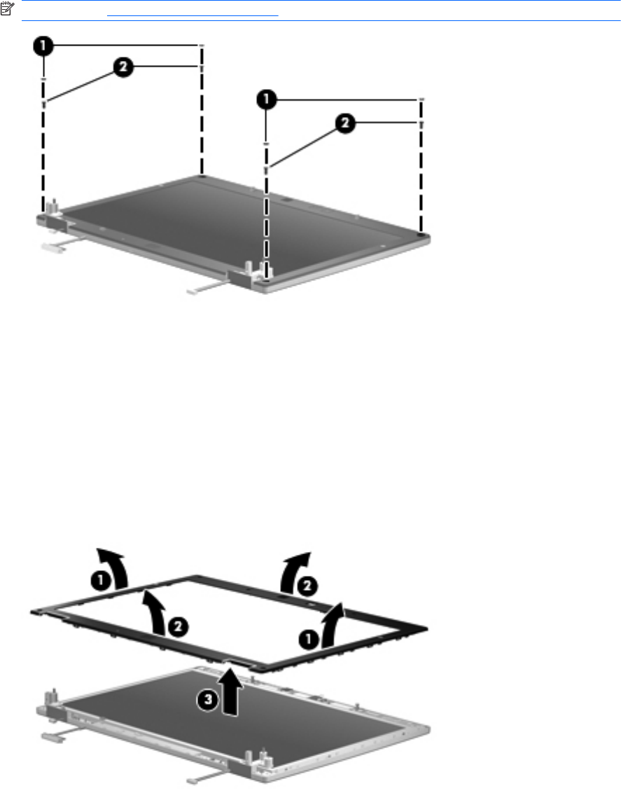
If it is necessary to replace the display bezel or display hinges, remove the four rubber screw
covers (1) and the four Phillips PM2.5×7.0 screws (2) that secure the display bezel to the display
assembly. The rubber screw covers are available in the Rubber Kit, spare part number
482966-001.
NOTE: See Display inverter on page 52 for procedures on removing the display inverter.
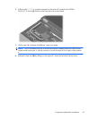
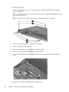
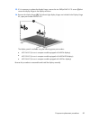
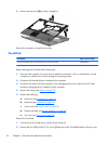
13. Flex the inside edges of the left and right sides (1) and the top and bottom sides (2) of the display
bezel until the bezel disengages from the display enclosure.
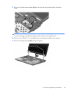
14. Remove the display bezel (3). The display bezel is available using spare part numbers:
●
488189-001 (for use in computer models equipped with non-LED displays and a webcam)
●
488190-001 (for use in computer models equipped with non-LED displays without a
webcam)
●
518420-001 (for use in computer models equipped with LED displays and a webcam)
●
518421-001 (for use in computer models equipped with LED displays without a webcam)
88 Chapter 4 Removal and replacement procedures