


Hardware options installation 43
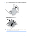
• Memory must be loaded in quads, with a pair of DIMMs in each memory cartridge for a corresponding
processor.
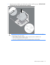
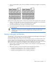
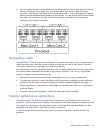
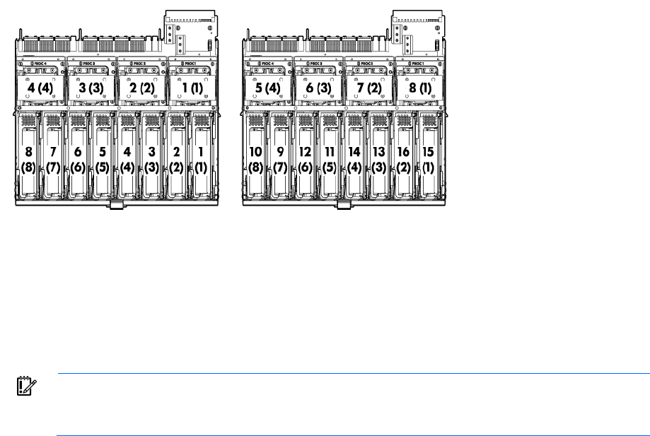
Upper processor memory board is shown on the left. Lower processor memory board is shown on the right.
• Memory is only accessible to the system if the associated processor is installed. Do not install memory
cartridges in cartridge slots without the corresponding processor installed.
• Two DIMM populated memory cartridges are required per processor.
• To maximize performance in multi-processor configurations, distribute the total memory capacity evenly
across all processors.
IMPORTANT: Be sure you are using the correct spare part number when replacing the memory
cartridge. The server ships with one of two different memory cartridges, which are not
interchangeable.
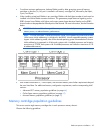
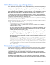
Memory subsystem architecture
The Intel® Xeon™ 7500 processor memory architecture is designed to take advantage of multiple stages of
memory interleaving to reduce latency and increase bandwidth.
Each Intel Xeon 7500 processor contains two memory controllers as shown in the illustration below. Each
memory controller has two SMI buses operating in Lockstep mode. Each SMI bus connects to a memory
buffer. The buffer converts SMI to DDR3 and expands the memory capacity of the system. Each buffer has two
DDR3 channels and can support up to four DIMMs for a total of eight DIMMs per cartridge.
• Memory speed is not affected by number of DIMMs or ranks. All DIMMs run at the highest possible
speed for a given processor.
• DDR3 memory speed is a function of the QPI bus speed supported by the processor:
o Processors with a QPI speed of 6.4 GT/s run memory at 1066 MT/s.
o Processors with a QPI speed of 5.6 GT/s run memory at 978 MT/s.
o Processors with a QPI speed of 4.8 GT/s run memory at 800 MT/s.