


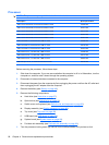
Fan/heat sink assembly
NOTE: The fan/heat sink assembly spare kit includes replacement thermal material.
Description Spare part number
For use only with computers equipped with graphics subsystems with discrete memory 532141-001
For use only with computers equipped with graphics subsystems with UMA memory 532142-001
NOTE: To properly ventilate the computer, allow at least a 7.6-cm (3-inch) clearance on the right side
and rear panel of the computer. The computer uses an electric fan for ventilation. The fan is controlled
by a temperature sensor and is designed to turn on automatically when high temperature conditions
exist. These conditions are affected by high external temperatures, system power consumption, power
management/battery conservation configurations, battery fast charging, and software requirements.
Exhaust air is displaced through the ventilation grill located on the left side of the computer.
Before removing the fan/heat sink assembly, follow these steps:
1. Shut down the computer. If you are unsure whether the computer is off or in Hibernation, turn the
computer on, and then shut it down through the operating system.
2. Disconnect all external devices connected to the computer.
3. Disconnect the power from the computer by first unplugging the power cord from the AC outlet and
then unplugging the AC adapter from the computer.
4. Remove the battery (see
Battery on page 48).
5. Remove the following components:
a. Hard drive (see
Hard drive on page 57).
b. Optical drive (see
Optical drive on page 51).
c. Switch cover and keyboard (see
Switch cover and keyboard on page 63).
d. Display assembly (see
Display assembly on page 68).
e. Top cover (see
Top cover on page 80).
f. USB board (see
USB board on page 85).
g. System board (see
System board on page 88).
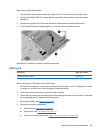
Remove the fan/heat sink assembly:
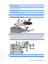
NOTE: Steps 1 through 5 apply only to models with discrete subsystem memory on the system board.
Steps 6 through 10 apply only to models with UMA subsystem memory on the system board.
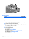
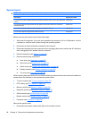
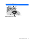
1. Turn the system board upside down, with the expansion port 3 and external monitor port toward
you.
2. Disconnect the fan cable (1) from the system board.
3. Loosen the three Phillips PM2.5×14.0 spring-loaded, captive screws (2), (3), and (4) that secure
the fan/heat sink assembly to the system board.
92 Chapter 4 Removal and replacement procedures