


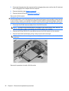
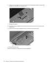

4. Remove the display assembly (2).
NOTE: Steps 5 through 27 provide display assembly internal component removal information for
computers equipped with AntiGlare display assemblies. See steps 28 through 38 for display
assembly internal component removal information for computers equipped with BrightView display
assemblies.
NOTE: See Webcam/microphone moduleon page 49 for webcam/microphone module
replacement instructions for computers equipped with BrightView display assemblies.
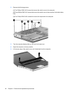
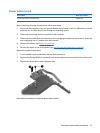
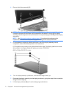
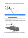
5. If it is necessary to replace the display enclosure or any of the display assembly internal
components, remove the following screw covers and screws:
(1) Two plastic screw covers on the display bezel bottom edge. The display plastic screw covers
are included in the Display Rubber Kit, spare part number 513479-001.
(2) Four Phillips PM2.5×7.0 screws.
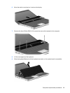
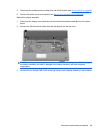
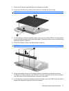
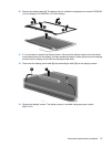
6. Turn the display assembly upside down, with the bottom edge toward you.
7. Disconnect the display assembly from the display enclosure by prying them apart from one another
along the bottom edge (1).
8. Lift the display enclosure (2) as far as the display logo cable allows.
70 Chapter 4 Removal and replacement procedures