


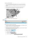
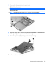
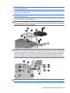
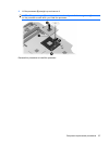

CAUTION: Loosen the screws in the order indicated by the callouts to ensure consistent pressure
over the processor board.
4. Loosen the three Phillips PM2.5×5.0 captive screws (5), (6), and (7) that secure the fan/heat sink
assembly to the system board.
CAUTION: Loosen the screws in the order indicated by the callouts to ensure consistent pressure
over the processor board.
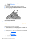
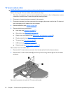
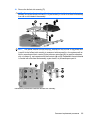
5. Remove the fan/heat sink assembly (8).
NOTE: Due to the adhesive quality of the thermal material located between the fan/heat sink
assembly and system board components, it may be necessary to move the fan/heat sink assembly
from side to side to detach the assembly.
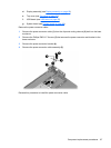
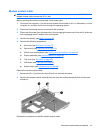
NOTE: The thermal material must be thoroughly cleaned from the surfaces of the fan/heat sink
assembly and the system board each time the fan/heat sink assembly is removed. Thermal paste
is applied to the fan/heat sink assembly to correspond with components on the system board as
follows: capacitors and their contacts (1) the processor and contact (2), the graphics subsystem
chip and contact (3), and capacitors and their contacts (4), (5) and (6). Replacement thermal
material is included with all fan/heat sink assembly, system board, and processor spare part kits.
NOTE: Steps 1 through 5 apply only to models with discrete subsystem memory on the system
board. Steps 6 through 10 apply only to models with UMA subsystem memory on the system board.
Component replacement procedures 93