


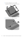
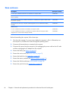
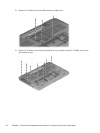
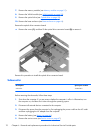
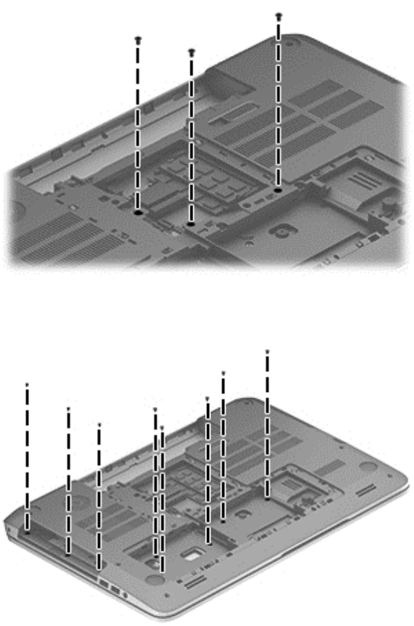
3. Remove 3 2x5-MM screws around the memory module area.
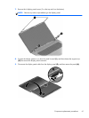
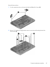
4. Remove 3 2x3-MM screws from the optical drive bay, and then remove 5 2x3-MM screws from
the hard drive bays.
66 Chapter 6 Removal and replacement procedures for Authorized Service Provider parts