


ECM-5510
26 ECM-5510 User’s Manual
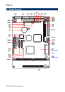
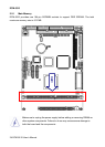
2.3 Jumper and Connector List
You can configure your board to match the needs of your application by setting jumpers. A
jumper is the simplest kind of electric switch.
It consists of two metal pins and a small metal clip (often protected by a plastic cover) that
slides over the pins to connect them. To “close” a jumper you connect the pins with the clip.
To “open” a jumper you remove the clip. Sometimes a jumper will have three pins, labeled 1,
2, and 3. In this case, you would connect either two pins.
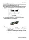
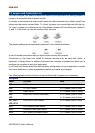
The jumper settings are schematically depicted in this manual as follows:
A pair of needle-nose pliers may be helpful when working with jumpers.
Connectors on the board are linked to external devices such as hard disk drives, a
keyboard, or floppy drives. In addition, the board has a number of jumpers that allow you to
configure your system to suit your application.
If you have any doubts about the best hardware configuration for your application, contact
your local distributor or sales representative before you make any changes.
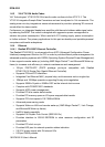
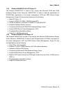
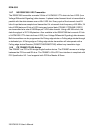
The following tables list the function of each of the board's jumpers and connectors.
Jumpers
Label Function Note
JP1
BIOS write protect select 3 x 1 header, pitch 2.54mm
JP2
TFT/CRT select 2 x 1 header, pitch 2.0mm
JP3
Clear CMOS 3 x 1 header, pitch 2.54mm
JP5
JP6
COM2 RS-232/422/485 select 3 x 2 header, pitch 2.0mm
4 x 3 header, pitch 2.0mm
JP7, JP8,
JP9, JP10
COM 2/4/3/1 pin 9 select 3 x 2 header, pitch 2.0mm
JP11
LCD inverter power select 3 x 1 header, pitch 2.0mm
JP13
Compact Flash mode select 2 x 1 header, pitch 2.54mm
JP14
DOC memory address select 2 x 1 header, pitch 2.0mm