


ECM-5510
56 ECM-5510 User’s Manual
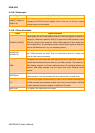
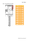
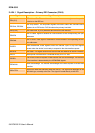
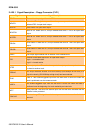
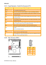
2.4.25.1 Signal Description – Floppy Connector (FLP1)
Signal Signal Description
RDATA The read data input signal from the FDD.
WDATA
Write data. This logic low open drain writes pre-compensation serial data to the
selected FDD. An open drain output.
WGATE Write enable. An open drain output.
MOATSA
Motor A On. When set to 0, this pin enables disk drive 0. This is an open drain
output.
MOTEB
Motor B On. When set to 0, this pin enables disk drive 1. This is an open drain
output.
DRVSA
Drive Select A. When set to 0, this pin enables disk drive A. This is an open drain
output.
DRVSB
Drive Select B. When set to 0, this pin enables disk drive B. This is an open drain
output.
SIDE1 This output signal selects side of the disk in the selected drive.
DIR
Direction of the head step motor. An open drain output
Logic 1 = outward motion
Logic 0 = inward motion
STEP
Step output pulses. This active low open drain output produces a pulse to move
the head to another track.
REDWC
This output indicates whether a low drive density (250/300kbps at low level) or a
high drive density (500/1000kbps at high level) has been selected.
TK00
Track 0. This Schmitt-triggered input from the disk drive is active low when the
head is positioned over the outermost track.
INDEX
This Schmitt-triggered input from the disk drive is active low when the head is
positioned over the beginning of a track marked by an index hole.
WPT
Write protected. This active low Schmitt input from the disk drive indicates that the
diskette is write-protected.
DSKCHG
Diskette change. This signal is active low at power on and whenever the diskette is
removed.