


ECM-5510
54 ECM-5510 User’s Manual
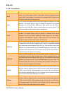
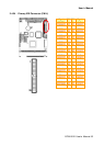
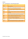
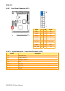
2.4.24.1 Signal Description – Primary IDE Connector (CN14)
Signal Signal Description
PDA [2:0]
IDE Address Bits. These address bits are used to access a register or data port in
a device on the IDE bus.
PDCS1#, PDCS3#
IDE Chip Selects. The chip select signals are used to select the command block
registers in an IDE device. DCS1# selects the primary hard disk.
PDD [15:0] IDE Data Lines. D [15:0] transfers data to/from the IDE devices.
PDIOR#
IDE I/O Read. Signal is asserted on read accesses to the corresponding IDE port
addresses.
PDIOW#
IDE I/O Write. Each signal is asserted on write accesses to corresponding the IDE
port addresses.
PIORDY
When deasserted, these signals extend the transfer cycle of any host register
access when the device is not ready to respond to the data transfer request.
RESET# IDE Reset. This signal resets all the devices that are attached to the IDE interface.
IRQ14 Interrupt line from hard disk. Connected directly to PC-AT bus.
PDREQ
The DREQ is used to request a DMA transfer from the South Bridge. The direction
of the transfers is determined by the IOR#/IOW# signals.
PDDACK#
DMA Acknowledge. The DACK# acknowledges the DREQ request to initiate DMA
transfers.
IDEACTP#
Signal from hard disk indicating hard disk activity. The signal level depends on the
hard disk type, normally active low. The signal is routed directly to the LED.