


User’s Manual
ECM-5510 User’s Manual
45
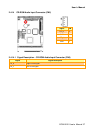
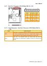
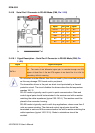
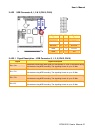
2.4.19.1 Signal Description – PC/104 Connector (CN7 + CN8)
2.4.19.1.1 Address
Signal Signal Description
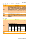
LA [17:23]
The address signals LA [23:17] define the selection of a 128KB section of memory
space within the 16MB address range of the 16-bit data bus. These signals are
active high. The validity of the MEMCS16# depends on these signals only. These
address lines are presented to the system with tri-state drivers. The permanent
master drives these lines except when an alternate master cycle occurs; in this
case, the temporary master drives these lines. The LA signals are not defined for
I/O accesses.
SA [0:19]
System address. Address lines for the first one Megabyte of memory. SA [9:0]
used for I/O addresses. SA0 is the least significant bit
SBHE#
This signal is an active low signal, that indicates that a byte is being transferred on
the upper byte (SD [15:8]) of the 16 bit bus. All bus masters will drive this line with
a tri-state driver.
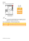
2.4.19.1.2 Data
Signal Signal Description
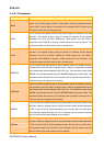
SD [0:7]
These signals are defined for the low order byte of the 16-bit data bus being the
only bus for 8 bit PC-AT/PC104 adapter boards. Memory or I/O transfers on this
part of the data bus are defined for 8-bit operations with even or odd addresses
and for 16-bit operations for odd addresses only. The signals SA0 and SBHE# are
used to define the data present on this bus:
SBHE# SA0 SD8-SD15 SD0-SD7 Action
0 0 ODD EVEN Word transfer
0 1 ODD ODD
Byte transfer on
SD8-SD15
1 0 X EVEN
Byte transfer on
SD0-SD7
1 1 X ODD
Byte transfer on
SD7-
SD [8:15]
These signals are defined for the high order byte of the 16-bit data bus. Memory or
I/O transfers on this part of the bus are defined when SBHE# is active.