


User’s Manual
ECM-5510 User’s Manual
47
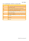
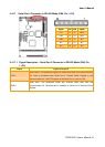
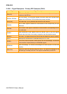
2.4.19.1.4 Transfer Response
Signal Signal Description
IOCS16#
This is an active low signal driven by an I/O-mapped PC-AT/PC104 adapter
indicating that the I/O device located at the address is a 16-bit device. This open
collector signal is driven, based on SA [15:0] only (not IOR# and IOW#) when AEN
is not asserted.
MEMCS16#
This is an active low signal driven by a memory mapped PC-AT/PC104 adapter
indicating that the memory device located at the address is a 16-bit device. This
open collector signal is driven, based on LA [23:17] only.
OWS#
This signal is an active low open-collector signal asserted by a 16-bit memory
mapped device that may cause an early termination of the current transfer. It
should be gated with MEMR# or MEMW# and is not valid during DMA transfers.
IOCHRDY precedes 0WS#.
IOCHRDY
This is an active high signal driven inactive by the target of either a memory or an
I/O operation to extend the current cycle. This open collector signal is driven based
on the system address and the appropriate control strobe. IOCHRDY precedes
0WS#.
IOCHCK#
This is an active low signal driven active by a PC-AT/PC104 adapter detecting a
fatal error during bus operation. When this open collector signal is driven low it will
typically cause a non-maskable interrupt.
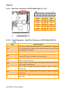
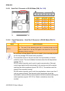
2.4.19.1.5 Control
Signal Signal Description
SYSCLK
This clock signal may vary in frequency from 2.5 MHz to 25.0 MHz depending on
the setup made in the BIOS. Frequencies above 16 MHz are not recommended.
The standard states 6 MHz to 8.33 MHz, but most new adapters are able to handle
higher frequencies. The PC-AT/PC104 bus timing is based on this clock signal.
OSC
This is a clock signal with a 14.31818 MHz ± 50 ppm frequency and a 50 ± 5%
duty cycle. The signal is driven by the permanent master.
RESETDRV
This active high signal indicates that the adapter should be brought to an initial
reset condition. This signal will be asserted by the permanent master on the bus
for at least 100 ms at power-up or watchdog time-out to ensure that adapters in the
system are properly reset. When active, all adapters should turn off or tri-state all
drivers connected to the bus.