


ECM-5510
62 ECM-5510 User’s Manual
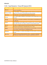
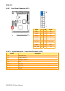
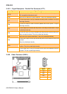
2.4.31.1 Signal Description – Parallel Port Connecter (LPT1)
Signal Signal Description
PD[7:0]
Parallel data bus from PC board to printer. The data lines are able to operate in
PS/2 compatible bi-directional mode.
SLIN# Output line for detection of printer selection. This pin is pulled high internally.
SLCT
An active high input on this pin indicates that the printer is selected. This pin is
pulled high internally.
STB#
An active low output is used to latch the parallel data into the printer. This pin is
pulled high internally.
BUSY
An active high input indicates that the printer is not ready to receive data. This pin
is pulled high internally.
ACK#
An active low input on this pin indicates that the printer has received data and is
ready to accept more data. This pin is pulled high internally.
INIT# Output line for the printer initialization. This pin is pulled high internally.
AFD#
An active low output from this pin causes the printer to auto feed a line after a line
is printed.
This pin is pulled high internally.
ERR#
An active low input on this pin indicates that the printer has encountered an error
condition. This pin is pulled high internally.
PE
An active high input on this pin indicates that the printer has detected the end of
the paper. This pin is pulled high internally.
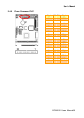
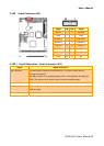
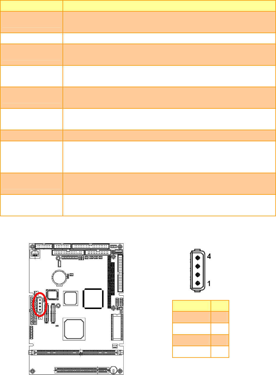
2.4.32 Power Connector (PWR1)
Signal PIN
+5V
4
GND
3
GND
2
+12V
1