


Chapter 3 Installing LH 4 Components
16
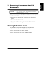
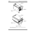
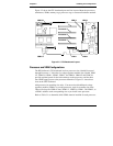
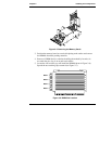
Figure 3-2 shows the CPU baseboard parts and slot layout without the processors,
terminators, VRMs, memory cage, processor cage, or structural hardware attached.
VRM 1
/
Processor 2
Processor 3
2
VRM1 VRM2
VRM 3
/
4
VRM 4
VRM 3
Processor 4
Processor 1
Figure 3-2. CPU Baseboard Layout
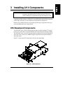
Processor and VRM Configurations
The HP NetServer’s CPU baseboard has four processor slots, labeled Processor 1
through Processor 4. It also has six voltage regulator module slots, labeled VRM
1/2, VRM 3/4, VRM 1, VRM 2, VRM 3, and VRM 4. VRM 1/2 and VRM 3/4
provide regulated power for the cache memory on the processors, and the other
four VRMs supply power to the processors themselves. Figure 3-1 shows these
slots on the CPU baseboard.
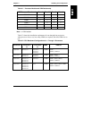
Add processors in ascending slot order. You must also add additional voltage
regulator modules (VRMs) as you add processors, again in ascending slot order.
There will always be VRMs in slots VRM 1/2 , VRM 3/4, VRM 1, and VRM 2, so
a VRM is added to each corresponding slot as you install a new processor.
Refer to Table 3-1 to determine which VRMs must be installed for each processor.