


Chapter 3 Installing LH 4 Components
17
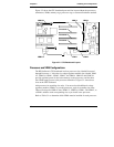
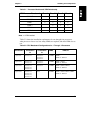
Table 3-1. Processor Module and VRM Relationship
VRM Name on Baseboard Proc 1 Proc 2 Proc 3 Proc 4
VRM 1/2 xxxx
VRM 3/4 xxxx
VRM 1 xxxx
VRM 2 xxx
VRM 3 x x
VRM 4 x
Note: x = VRM installed
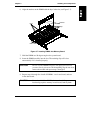
Table 3-2 shows the installation requirements for one through four processors:
what processor slots to use, how many VRMs are required, and what VRM slots to
use.
Table 3-2. CPU Baseboard Configurations for 1 Through 4 Processors
Processors Processors
In:
Terminators
In:
VRMs VRMs In:
1 processor Processor 1 Processor 2,
Processor 3,
Processor 4
3 VRMs VRM 1,
VRM 1/2, VRM 3/4
2 processors Processor 1,
Processor 2
Processor 3,
Processor 4
4 VRMs VRM 1, VRM 2,
VRM 1/2, VRM 3/4
3 processors Processor 1,
Processor 2,
Processor 3
Processor 4 5 VRMs VRM 1, VRM 2, VRM 3,
VRM 1/2, VRM 3/4
4 processors Processor 1,
Processor 2,
Processor 3,
Processor 4
None 6 VRMs VRM 1, VRM 2, VRM 3, VRM 4,
VRM 1/2, VRM 3/4