


Chapter 3 Installing LH 4 Components
24
Installing the CPU Baseboard in the Chassis
The LH 4 CPU baseboard fits into the chassis snugly. Observe these precautions:
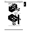
• Check to make sure that you have removed the card guide and air baffle for
the LH 3 CPU baseboard. If it is still installed, it will prevent the LH 4
board from seating properly. See "Removing the CPU Baseboard Guide
and Air Baffle" earlier in this manual, and refer to Figure 2-2.
• Check to see that the covers for the processor cage and memory cage are
screwed on, and that the VRMs are seated properly.
• The edge of the CPU baseboard that faces the rear of the LH 4 has a thin
metal liner that protects against radio frequency interference. This material
may snag on the chassis edge and crumple. If you have problems seating
the board, check to see if the metal liner is catching on the chassis.
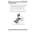
1. Use two people to lift the CPU baseboard, one holding each end. One
person can do it, but it’s easier with a person on each end.
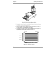
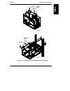
2. Raise the ejection levers into a vertical position, as shown in Figure 3-8.
Slide the CPU baseboard into place. In the LH 4 (pedestal) configuration,
lower it from the top of the LH 4. In the LH 4r (rack) configuration, slide
it in gently from the side.
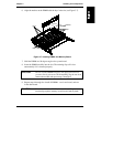
CAUTION The side of the CPU baseboard facing the front of the LH 4
fits into the long black guide slot mounted to the chassis. The
side of the CPU baseboard facing the rear of the LH 4 fits into
two slots that frame the connectors on the rear edge of the
CPU baseboard. Note the metal liner around the edge of the
CPU baseboard and be careful not to snag it on the chassis.
See Figure 3-9.