5–22 Maintenance and Service Guide
Removal and Replacement Procedures
5.11 Keyboard Assembly
1. Prepare the computer for disassembly (Section 5.3).
2. Remove the memory module/Mini Card module
compartment cover (Section 5.6).
3. Remove the switch cover (Section 5.10).
4. Turn the computer upside down with the rear panel
toward you.
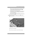
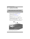
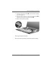
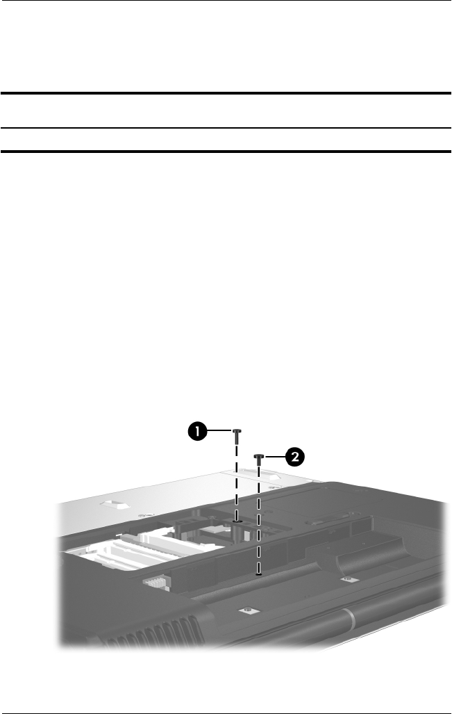
5. Remove the Phillips PM2.5×13.0 screw 1 in the memory
module/Mini Card module compartment that secures the
keyboard assembly to the computer.
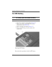
6. Remove the silver Phillips PM2.5×6.0 screw 2 in the battery
bay that secures the keyboard assembly to the computer.
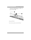
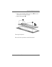
Removing the Keyboard Assembly Screws
Keyboard Assembly Spare Part Number Information
Keyboard assembly frame 403818-001


