


5–34 Maintenance and Service Guide
Removal and Replacement Procedures
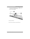
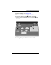
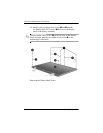
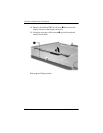
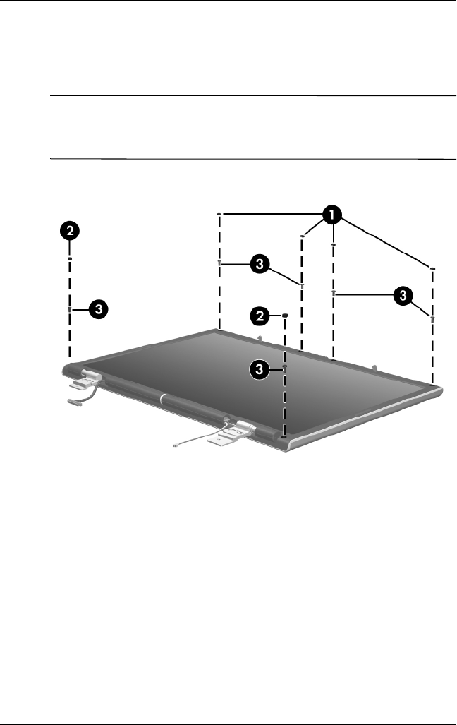
10. Remove the six rubber screw covers 1 and 2 and the
six Phillips PM2.5×7.0 screws 3 that secure the display
bezel to the display assembly.
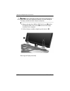
✎
The four rubber screw covers 1 on the top edge of the display
bezel are larger than the two rubber screw covers 2 on the
bottom edge of the bezel.
Removing the Display Bezel Screws