


5–50 Maintenance and Service Guide
Removal and Replacement Procedures
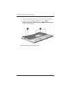
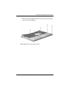
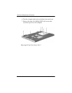
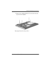
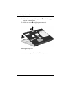
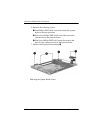
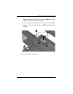
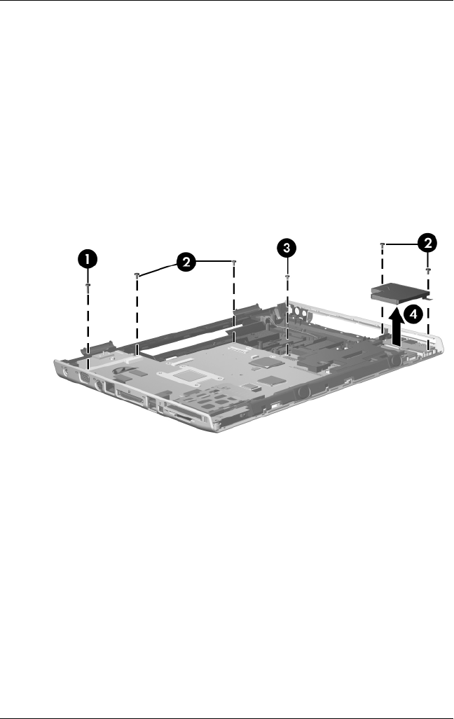
6. Remove the following screws:
1 One Phillips PM2.5×9.0 screw that secures the system
board to the base enclosure
2 Four silver Phillips PM2.5×6.0 screws that secure the
system board to the base enclosure
3 One silver Phillips PM2.5×6.0 screw that secures the
optical drive connector board to the base enclosure
7. Remove the ExpressCard assembly 4.
Removing the System Board Screws