


Removal and Replacement Procedures
Maintenance and Service Guide 5–65
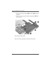
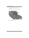
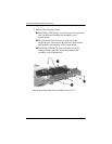
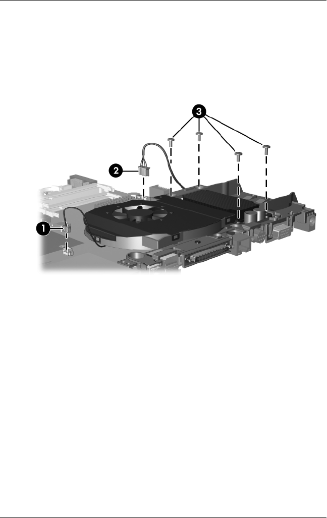
2. Disconnect the fan cable 1 and the power connector cable 2
from the system board.
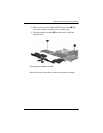
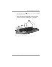
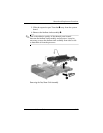
3. Remove the four silver Phillips PM2.5×6.0 screws 3 that
secure the fan/heat sink assembly to the system board.
Removing the Fan/Heat Sink Assembly Screws, Part 1