


Removal and Replacement Procedures
Maintenance and Service Guide 5–3
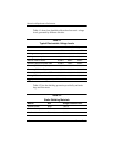
5.2 Disassembly Sequence Chart
Use the chart below to determine the section number to be
referenced when removing computer components.
Disassembly Sequence Chart
Section Description
# of Screws Removed
5.3 Preparing the Computer for
Disassembly
Battery pack 0
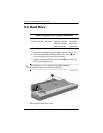
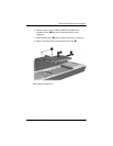
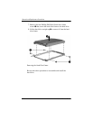
5.4 Hard Drive 3 loosened to remove the
hard drive cover
4 to remove the hard drives
8 to remove the hard drive
frames
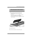
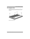
5.5 Computer Feet 0
5.6 Memory Module 2 loosened to remove the
memory module/Mini Card
module compartment cover
5.7 Mini Card Module 0
Å
To prevent an unresponsive system and the display of a
warning message, install only a Mini Card device
authorized for use in your computer by the governmental
agency that regulates wireless devices in your country. If
you install a device and then receive a warning message,
remove the device to restore computer functionality. Then
contact Customer Care.
5.8 RTC Battery 0
5.9 Optical Drive 1 to remove the optical drive
2 to remove the optical drive
bracket
5.10 Switch Cover 5
5.11 Keyboard Assembly 2