


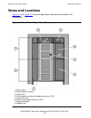


Overview of the Tape Library
SL500 (M852x) Tape Library Installation and User’s Guide—541531-006
1-4
Physical Configurations
Physical Configurations
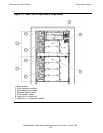
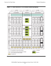
Figure 1-3 on page 1-5 shows a tape library with only a base module. Figure 1-4 on
page 1-6 shows a tape library with a base module that has nine reserved slots, one
drive expansion module, and one cartridge expansion module.
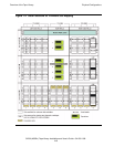
Figure 1-5 on page 1-7 shows a tape library with a base module that has two reserved
slots, one drive expansion module, and one cartridge expansion module.
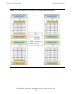
Figure 1-6 on page 1-8 shows the slot capacity of a cartridge expansion module
according to which type of module is installed above and below it.
The numbering scheme uses the tape library, module, row and column scheme. Four
integers are used to represent the cartridge and tape drive slots, as viewed from the
front of the tape library.
1. Library number (always 0)
2. Library module number 1 (top of rack) through 5 (bottom of rack)
3. Row number 1 through 9 (base module) or 1 through 12 (expansion module)
4. Column number 1 through 9 for base module and drive expansion module, 1
through 11 for cartridge expansion module
Note. In Figure 1-5 on page 1-7, all six tape drives are installed. When only some of the tape
drives are installed, only those that are powered-on receive SCSI addresses, starting with the
top-most tape drive.
The storage slot numbering begins with the first slot after the reserved slots in column 1.
Figure 1-5
on page 1-7 shows two reserved slots, but there could be more. If the reserved slots
are configured as storage slots, the top slot (row 1) would be 1. If the CAP in module 1 is
configured as storage slots, the top CAP slot (row 1) is 62 if there are two reserved slots as
shown, or 64 if no slots are reserved.