


Contents
SL500 (M852x) Tape Library Installation and User’s Guide—541531-006
iii
A. Specifications
A. Specifications
Tape Library Components Weights A-3
Tape Library Environment A-3
Power A-4
Safety and Compliance
Figures
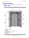
Figure 1-1. Front View of Tape Library Components 1-2
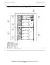
Figure 1-2. Back View of Tape Library Components 1-3
Figure 1-3. Base Module Slots 1-5
Figure 1-4. Slots Locations for Firmware Slot Mapping 1-6
Figure 1-5. Slots Locations for SCSI Element Numbering Mapping 1-7
Figure 1-6. Slot Capacity for Back Wall of Cartridge Expansion Module 1-8
Figure 1-7. Robotics Components 1-12
Figure 1-8. Hand Assembly 1-13
Figure 1-9. Supported Tape Drives 1-16
Figure 1-10. Tape Library Interfaces Locations 1-18
Figure 2-1. Buttons and Indicators 2-2
Figure 3-1. Sliding a Magazine Into a CAP 3-2
Figure 3-2. Lever Not in Parked Position 3-4
Figure 3-3. Door Locking Lever Extended 3-5
Figure 3-4. Moving Robotics Park Lever 3-6
Figure 3-5. Inserting Cartridges Into Slots 3-7
Figure 3-6. Inserting Cartridge Into Tape Drive 3-8
Figure 3-7.
Location of Unload Button 3-9
Figure 3-8.
Manual Release Screw 3-11
Figure 4-1. Ultrium Cartridge Components 4-3
Figure 4-2. LTO Cartridge Labels 4-4
Figure 4-3.
Ultrium Cartridge Label 4-5
Figure 4-4.
Write-Protect Switch 4-6
Figure 7-1.
Configuration Example 7-2
Figure A-1.
Library and Rack Dimensions A-1
Figure A-2. Tape Library and Rack Dimensions A-2
Figure A-3. Power Cabling A-6
Tables
Table 1-1. Cartridge Slot and Tape Drive Capacities 1-10
Table 1-2. LTO Generation 3 Specifications 1-16
Table 2-1. Keypad Buttons and Indicators 2-3