


Appendix B Host Computer Interface
B-2
[ ]: Signal names in the Auto mode and Nibble (high) mode (IEEE1284).
In the Auto mode and Nibble (high) mode, these signals are bi-
directional.
Detailed descriptions of the signals follow.
Strobe* [nStrobe] (Pin 1)
A negative-going Strobe* pulse causes the printer to read and
latch the data on the Data 0 [1] to Data 7 [8] signal lines.
Data 0 [1] to Data 7 [8] (Pins 2 to 9)
These eight signals form the data byte sent from the host
computer to the printer. Data 7 [8] is the most significant bit.
Acknowledge* [nAck] (Pin 10)
This negative-going pulse acknowledges the previous charac-
ter received by the printer.
Busy [Busy] (Pin 11)
This signal is high when the printer is busy and low when it
is able to accept more data.
Paper Empty [PError] (Pin 12)
This signal goes high when the printer has received a print
job and run out of paper.
Online [Select] (Pin 13)
This signal is high when the printer is online and low when
the printer is offline. It goes low when the GO key is pressed
to set the printer offline.
+5 V DC (Pin 18)
This line is connected to the printer’s +5 V DC line (+5 V ±0.5
V, maximum 400 mA [Serial and Parallel total], fused).
Error* [nFault] (Pin 32)
When the high-speed parallel line control is on (FRPO O2=2),
this line returns error status.
Power Ready (Pin 35)
This signal is high when the printer is turned on.
The Paper Empty, Online, and Error signals are not used un-
less enabled by the FRPO command (O2 parameter).
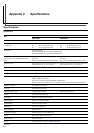
This printer supports the Hi-Speed USB 2.0. USB (Universal
Serial Bus) interface specifications and interface signals are
as follows.
Basic specification
Complies with the Hi-Speed USB 2.0.
Connectors
Printer: B-type receptacle (female) with upstream port
Cable: B-type plug (male)
Cable
Use a shielded cable that complies with USB 2.0 and not long-
er than 5 meters (16 feet).
Transfer Mode
Full speed (max. 480 Mbps)
Power Control
Self-power device
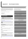
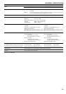
USB Connector Pin Assignment
NOTE
2. USB Interface
2.1 Specifications
2.2 Interface Signals
Pin Signal Description
1 Vbus Power supply (+5 V)
2 D- Data transmission
3 D+ Data transmission
4 GND Signal ground
Shell Shield
Table B-2