


Appendix B Host Computer Interface
B-4
H5: Protocol logic
The factory default setting is 0.
H6: Buffer nearly-full threshold
This is a percentage from 0 to 99. The factory default setting
is 90.
H7: Buffer nearly-empty threshold
This is a percentage from 0 to 99. The factory setting is 70.
The factory default settings of the buffer nearly-full and near-
ly-empty thresholds (H6 and H7) are subject to change with-
out notification.
The gap between the nearly-full and nearly-empty thresholds
allows the computer to send a fairly large amount of data in
a continuous stream.
H8: Received-data buffer size
This is the size of the input buffer, specified in units of 10
Kbytes. The factory-set value is 6, meaning 60 Kbytes.
The PRESCRIBE FRPO D0 command provides control over
XON/XOFF operation when an error occurs on the serial in-
terface. The following table summarizes the error status cor-
responding to different D0 values.
Make sure that the RS-232C cable is wired correctly. The ca-
ble must be a null modem cable; that is, one in which pin 2 on
either end of the cable is connected to pin 3 on the other end.
You cannot use a straight cable such as IBM communication
adapter cable type 1502067 unless you purchase a null mo-
dem adapter.
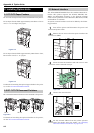
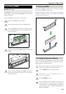
Remove the plastic cover from the printer end of the
cable.
Next to each of the wires inside the cable is a bare
shield wire. Solder all these shield wires together
into a single bundle.
Using a section of flat wire about 3 mm wide and 15
mm long, connect the bundle of shield wires to the
metal facing of the connector. Check that the solder
connections are secure.
Desolder wires 2 and 3, then resolder them in
crossed configuration. Solder wire 2 to pin 3 and
wire 3 to pin 2. Cover the solder joints with ther-
mofit tube.
Cut wires 4, 5, 6, and 20.
Solder wires 5 and 6 together and connect them to
pin 20. Cover the solder joints with a thermofit tube.
Leave wire 4 unconnected.
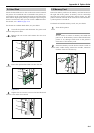
Tape all remaining loose ends, or seal them with a
thermofit tube.
Attach the plastic cover back on.
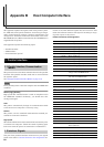
Check that the power of both the printer and the computer is
switched off.
Discharge yourself of static electricity by touching a
metal object such as a doorknob.
Remove the plastie cap from the printer’s RS-232C
interface connector.
Plug the printer end of the RS-232C interface cable
into the printer’s RS-232C connector and screw it in
place.
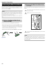
Plug the other end of the cable into the computer’s
RS-232C interface connector.
Switch on the printer’s power.
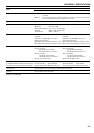
Parameter value Meaning
0 Combination of 1 and 3 below
1DTR/DSR, positive logic
2 DTR, negative logic
3 XON/XOFF
4ETX/ACK
5 XON/XOFF recognized only as protocol
Table B-6
4.1 PRESCRIBE FRPO D0 command
Timing of XON transfer to host
while Ready or Waiting
Serial interface error
Error
not resolved
Error
resolved
XON sent every 3 to 5 seconds D0=0
(default)
D0=1
XON not sent D0=10 D0=11
Table B-7
5. RS-232C Cable Connection
5.1 Obtain a Suitable RS-232C Cable
5.2 Connecting the Printer to the Computer
1
2
3
4
5
6
7
8
1
2
3
4
5