


Travelstar 5K160 (SATA) Hard Disk Drive Specification
45/167
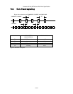
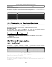
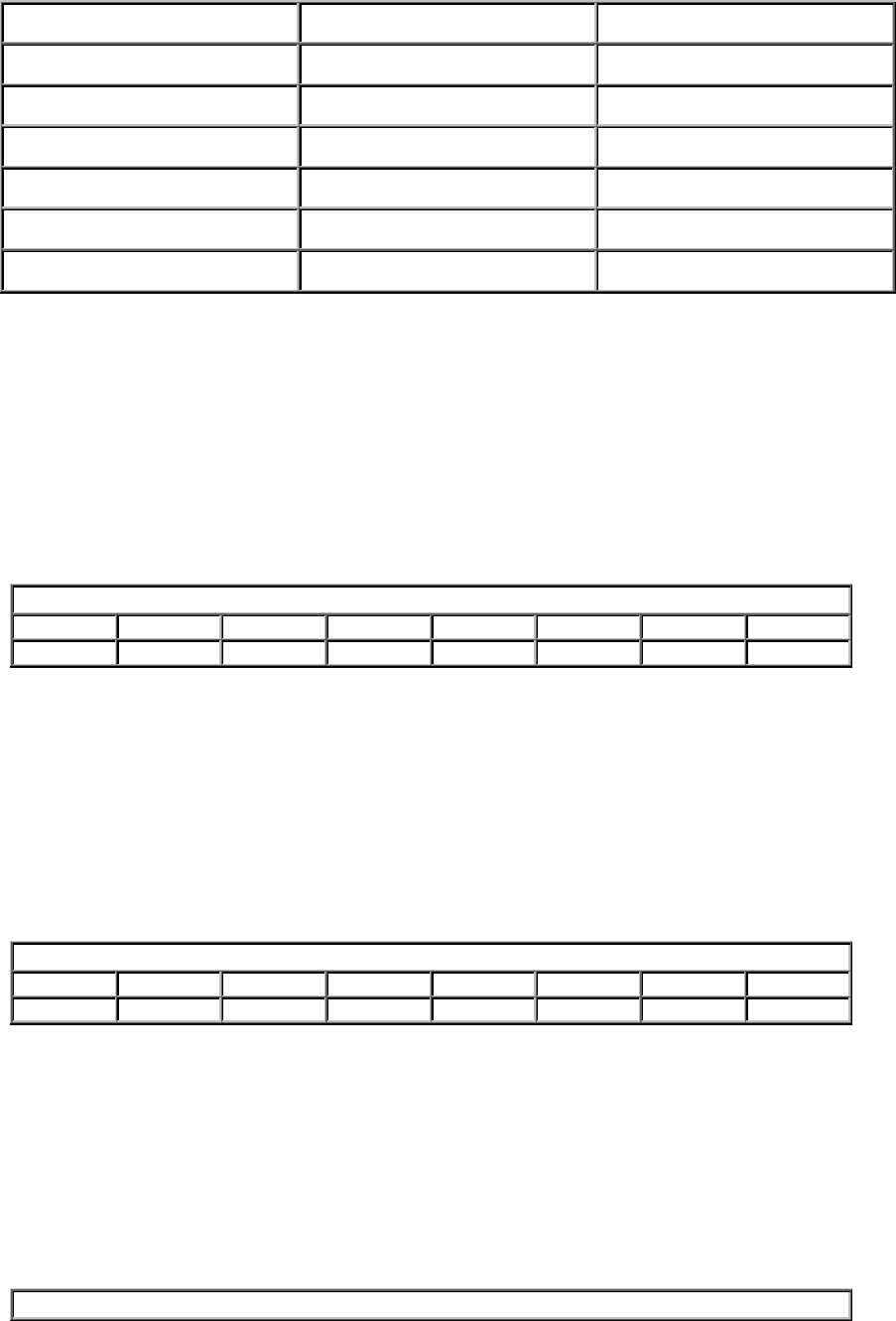
Cylinder high LBA high current LBA mid HOB=0
Cylinder high (exp) LBA high previous LBA mid HOB=1
Device/head Device Device
Command Command N/A
Control Device Control N/A
Status N/A Status
Error N/A Error
Table 24. Register naming convention and correspondence
11.2 Command register
This register contains the command code being sent to the device. Command execution begins
immediately after this register is written. The command set is shown in “Command set” on 5.
All other registers required for the command must be set up before writing the Command Register.
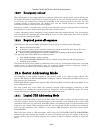
11.3 Device Control Register
Device Control Register
7 6 5 4 3 2 1 0
- - - - 1 SRST -IEN 0
Table 25. Device Control Register
Bit Definitions
SRST (RST)
Software Reset. The device is held reset when RST=1. Setting RST=0 reenables the device.
The host must set RST=1 and wait for at least 5 microseconds before setting RST=0, to
ensure that the device recognizes the reset.
-IEN
Interrupt Enable. When IEN=0, and the device is selected, device interrupts to the host will
be enabled. When IEN=1, or the device is not selected, device interrupts to the host will be
disabled.
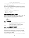
11.4 Device Register
Device Register
7 6 5 4 3 2 1 0
- L - 0 HS3 HS2 HS1 HS0
Table 26. Device Register
This register contains the device and head numbers.
Bit Definitions
L
Binary encoded address mode select. When L=0, addressing is by CHS mode. When L=1,
addressing is by LBA mode.
HS3,HS2,HS1,HS0
The HS3 through HS0 contain bits 24-27 of the LBA. At command completion, these bits are
updated to reflect the current LBA bits 24-27.
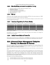
11.5 Error Register
Error Register