


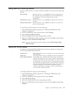
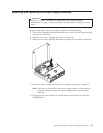
8.
Disconnect
all
other
cables
connected
to
the
system
board.
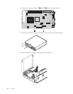
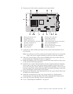
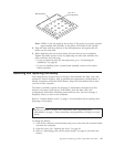
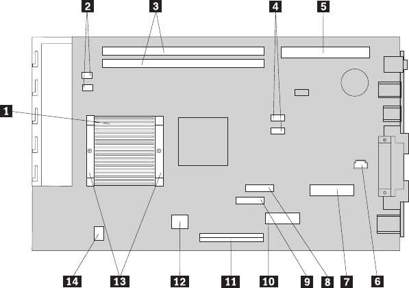
1
Microprocessor
heat
sink
8
Diskette
drive
connector
2
Fan
connectors
(2)
9
Front
panel
connector
3
DIMM
connectors
(2)
10
Power
connector
(P1)
4
SATA
1
IDE
and
SATA
2
IDE
hard
disk
drive
connectors
(2)
11
PATA
Primary
IDE
connector
(hard
disk
drive
and
CD-ROM
drive)
5
PCI
riser
connector
12
Power
connector
(P2)
6
Speaker
connector
13
Microprocessor
heat
sink
clamps
7
POV
connector
14
CD
audio
connector
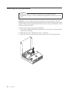
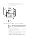
9.
Using
the
two
blue
handles
provided,
lift
the
system
board
assembly
out
of
the
computer.
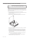
Note:
You
will
have
to
tilt
the
system
board
assembly
and
move
it
around
the
edge
of
the
power
supply
assembly
to
remove
it
from
the
computer.
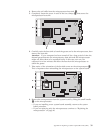
10.
Take
note
of
the
location
of
the
memory
DIMMs
and
remove
them
from
the
system
board.
See
“Installing
memory”
on
page
14.
11.
Install
the
DIMMs
on
the
new
system
board
in
the
same
location
as
they
were
on
the
system
board
being
replaced.
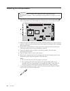
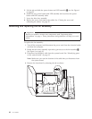
12.
Install
the
new
system
board
assembly
into
the
computer
chassis
by
aligning
the
two
tabs
on
the
rear
of
the
system
board
assembly
with
the
slots
in
the
rear
of
the
computer
chassis.
Slide
the
system
board
assembly
to
the
rear
until
the
front
edge
of
the
system
board
assembly
fits
behind
the
flange
in
the
front
and
is
seated
flush
to
the
bottom
of
the
chassis.
13.
Reconnect
all
cables
that
were
disconnected
from
the
system
board.
Make
sure
all
cables
are
routed
correctly.
14.
Install
the
microprocessor
on
the
new
system
board.
See
“Replacing
the
microprocessor”
on
page
40.
Return
here
after
replacing
the
microprocessor.
15.
Lower
the
drive
bay
assembly
into
the
normal
position.
16.
Go
to
“Completing
the
installation”
on
page
46.
Appendix
A.
Replacing
customer
replaceable
units
(CRU)
37