


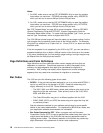
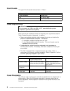
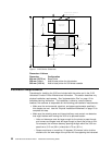

Operating
Position
Service
Position
91 cm
(3 6 in.)
Side
Stacker
129.5 cm
(5 1 in .)
15 cm (6 in.)
76 cm
(3 0 in.)
285.1 cm (112.25 in.)
76 cm
(3 0 in.)
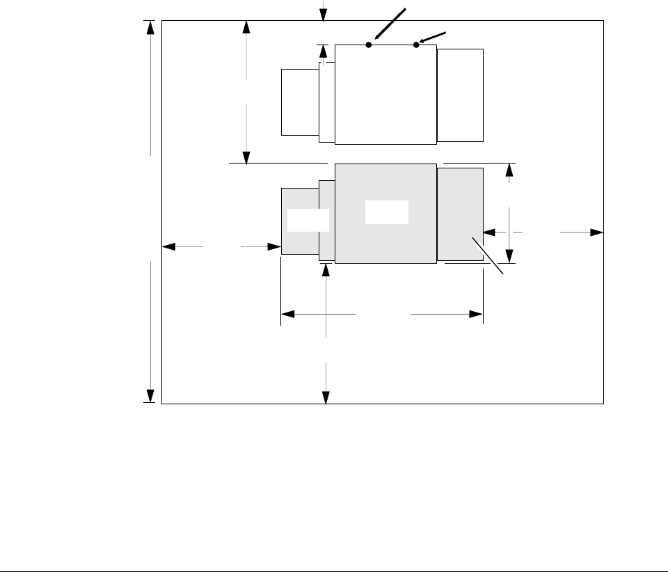
Dim ension
A
64.1 cm
(2 5 .2 5 in.)
500-sheet
C a s se tte
Power Cable
Location
CO8M 0001
A tta c h m e n t In te rfa c e
Cable Location
Figure 1. 3130 Service Clearances
Dimension A Values:
Dimension Configuration
654 mm (25.75 in.) Base printer
356 mm (14 in.) Add to base printer for side stacker
343 mm (13.5 in.) Add to base printer for 500-sheet cassette
Installation Requirements
Procedures for installing the 3130 are included with the printer and in the
3130
Advanced Function Printer: Maintenance Information
. This section describes only
physical installation requirements. See “Implementation Plan” on page 10 for
complete planning information. The installation is done by a service person;
however, the customer is responsible for the following pre-installation requirements:
Make sure the environmental, electrical, and space requirements specified in
this chapter are met. Use the “Physical Installation Worksheet” on page 23 to
complete this step.
Make sure the receiving area and internal delivery route contain no obstacles
that might interfere with moving the 3130 to its planned location.
– Halls and doorways must be large enough for the printer to pass through,
and corners and angles must be large enough to permit the printer to turn.
For example, the minimum doorway opening through which the 3130 can
pass from a 91.5 cm (36 in.) wide aisle is 75 cm (30 in.).
– Ramps must have no more than 12 degrees, 50 minutes incline to allow
clearance for the lower edge of the printer with its supporting feet retracted.
22 3130 Advanced Function Printer: Introduction and Planning Guide