


General information/installation Connections
11
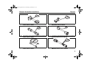
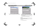
1.5. Connections
CAUTION
The work MUST be completed in the following sequence.
– Connect the 9-pin plug or the USB plug (both cables are supplied)
to a vacant serial port (COM1 or COM2) or a vacant USB port on the
PC (the plug can remain connected if necessary).
– Connect the 9-pin plug or USB plug to the diagnostic adapter.
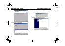
NOTE
The system must be switched manually between COM1 and COM2
(if the PC has more than one serial port). There is no need to switch
between the COM and USB ports manually. The USB port to which the
hardware is connected will be recognised automatically. This applies
even if there is more than one USB port.
Both COM and USB connections are not allowed to be used at the same
time.
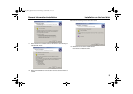
CAUTION
To avoid potential differences the vehicle must not be connected to a
charger during the diagnostic procedure.
CAUTION
Before connecting to the heater ensure that there is no voltage between
the earths of the PC and the vehicle. Voltages in excess of 5 V may
damage both the diagnostic adapter and the PC.
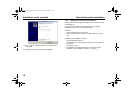
First connect the adapter to the positive pole and then to the earth to
ensure this.
– Connect the type-specific test adapter to the 4-pole connector of the
diagnostic adapter and the heater. The heater may be switched on.
NOTE
The connection cable to the heater is not allowed to be routed near the
vehicle ignition system or activated electrical devices (e.g. electric drill).
– Exit the diagnostic program before disconnecting the cables. No
particular sequence must be observed for disconnecting the cables.
101493_PCTe_gb.book Seite 11 Donnerstag, 16. Juni 2005 11:47 11