


I-8091 User Manual Version 1.0 06/2001
http://www.icpdas.com 2-14 ICPDAS
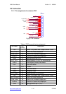
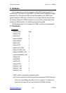
2.5 Connection
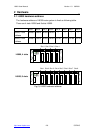
2.5.1 Pin assignment of connector CN2
EXT_GND
EXT_VCC (12~24V)
GND
+5V
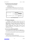
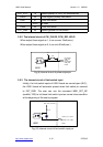
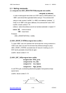
CN2
DB25M-90
13
25
12
24
11
23
10
22
9
21
8
20
7
19
6
18
5
17
4
16
3
15
2
14
1
LS24
ORG2
CCW_DIR2
CW_PULSE2
CW_PULSE1
LS14
HOLD1
LS21
LS11
HOLD2
EMG
CCW_DIR1
ORG1
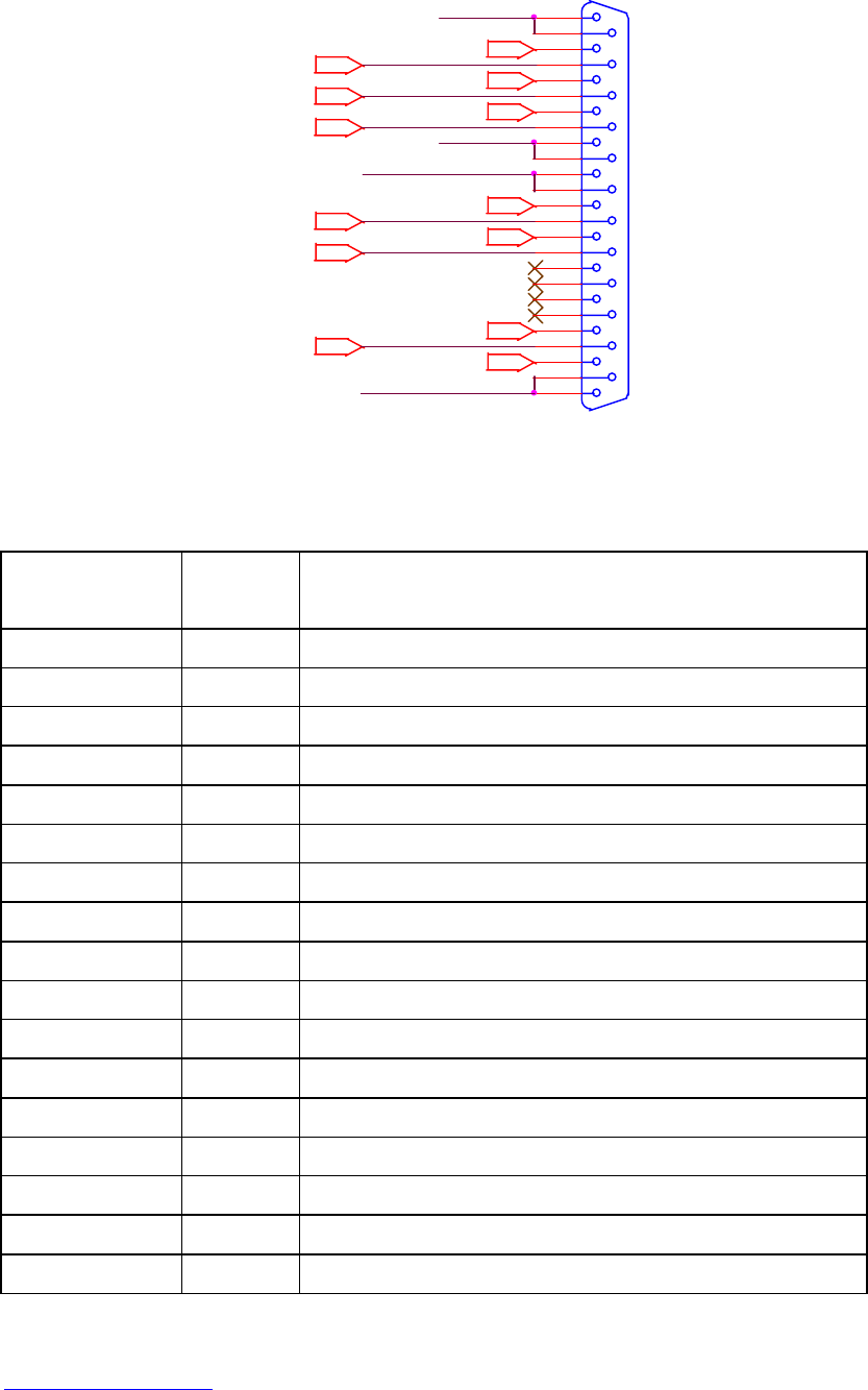
Fig.(8) CN2 connector
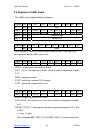
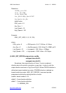
Table of CN2 connector’s pin assignment
pin name pin
number
Description
+5V 1 Internal +5V power, Max. output current: 50mA
CW_PULSE1 2 X-axis CW (Pulse) output pin
CCW_DIR1 3 X-axis CCW (Direction) output pin
HOLD1 4 X-axis HOLD (servo on) output pin
GND 5 Signal ground of pin 2,3,4
EXT_VCC 6 External power(12~24V) for limit switches
/ORG1 7 X-axis original (home) limit switch
/LS11 8 X-axis limit switch
9,10 No used
/LS14 11 X-axis limit switch
/EMG 12 Emergency input
EXT_GND 13 External ground for limit switch
+5V 14 Internal +5V power, Max. output current: 50mA
CW_PULSE2 15 Y-axis CW (Pulse) output pin
CCW_DIR2 16 Y-axis CCW (Direction) output pin
HOLD2 17 Y-axis HOLD (servo on) output pin
GND 18 Signal ground of pin 15,16,17