Processor Thermal/Mechanical Information
Thermal and Mechanical Design Guidelines 19
2.2.1 Processor Junction Temperature
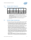
Table 2. Thermal Specifications for Intel
®
Celeron
®
Processor 200 Sequence
Symbol
Processor
Number
Core
Frequency
and
Voltage
Cache
Thermal Design
Power
(W)
Notes
TDP 220 1.20 GHz 512 KB 19 1, 4, 5
Symbol Parameter Min Max Notes
T
J
(°C) Junction Temperature 0 °C 100 °C 3, 4
NOTE:
1. The TDP is not the maximum theoretical power the processor can generate.
2. Not 100% tested. These power specifications are determined by characterization of the
processor currents at higher temperatures and extrapolating the values for the
temperature indicated.
3. As measured by the activation of the on-die Intel
®
Thermal Monitor. The Intel Thermal
Monitor’s automatic mode is used to indicate that the maximum T
J
has been reached.
Refer to datasheet for more details.
4. The Intel Thermal Monitor automatic mode must be enabled for the processor to
operate within specifications, please refer to datasheet for more details.
5. At T
J
of 100 °C.
2.3 Heatsink Design Considerations
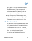
To remove the heat from the processor, three basic parameters should be considered:
• The area of the surface on which the heat transfer takes place. Without
any enhancements, this is the surface of the processor die. One method used to
improve thermal performance is by attaching a heatsink to the die. A heatsink
can increase the effective heat transfer surface area by conducting heat out of the
die and into the surrounding air through fins attached to the heatsink base.
• The conduction path from the heat source to the heatsink fins. Providing a
direct conduction path from the heat source to the heatsink fins and selecting
materials with higher thermal conductivity typically improves heatsink
performance. The length, thickness, and conductivity of the conduction path from
the heat source to the fins directly impact the thermal performance of the
heatsink. In particular, the quality of the contact between the package die and
the heatsink base has a higher impact on the overall thermal solution performance
as processor cooling requirements become stricter. Thermal interface material
(TIM) is used to fill in the gap between the die and the bottom surface of the
heatsink, and thereby improve the overall performance of the stack-up (die-TIM-
Heatsink). With extremely poor heatsink interface flatness or roughness, TIM may
not adequately fill the gap. The TIM thermal performance depends on its thermal
conductivity as well as the pressure applied to it. Refer to Section
2.3.3 for
further information.
• The heat transfer conditions on the surface on which heat transfer takes
place. Convective heat transfer occurs between the airflow and the surface
exposed to the flow. It is characterized by the local ambient temperature of the


