


Thermal Metrology
30 Thermal and Mechanical Design Guidelines
To determine the required heatsink performance, a heatsink solution provider would
need to determine Ψ
JS
performance for the selected TIM and mechanical load
configuration. If the heatsink solution were designed to work with a TIM material
performing at Ψ
JS
≤ 0.50 °C/W, solving for Equation 3 from above, the performance of
the heatsink would be:
Ψ
SA
= Ψ
JA
− Ψ
JS
= 1.75 − 0.50 = 1.25 °C/W
The heatsink temperature requirement can be obtained from Equation 4.
T
S-TOP-MAX
= (Ψ
jA
− Ψ
jS
− Ψ
HS_BASE
) × P
D
+ T
A
= (1.25 – 0.30) × 20 + 55 = 74 °C
3.2 Local Ambient Temperature Measurement
Guidelines
The local ambient temperature T
A
is the temperature of the ambient air surrounding
the processor. For a passive heatsink, T
A
is defined as the heatsink approach air
temperature; for an actively cooled heatsink, it is the temperature of inlet air to the
active cooling fan.
It is worthwhile to determine the local ambient temperature in the chassis around the
processor to understand the effect it may have on the die temperature.
T
A
is best measured by averaging temperature measurements at multiple locations in
the heatsink inlet airflow. This method helps reduce error and eliminate minor spatial
variations in temperature. The following guidelines are meant to enable accurate
determination of the localized air temperature around the processor during system
thermal testing.
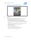
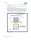
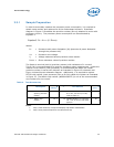
For active heatsinks, it is important to avoid taking measurement in the dead flow
zone that usually develops above the fan hub and hub spokes. Measurements should
be taken at four different locations uniformly placed at the center of the annulus
formed by the fan hub and the fan housing to evaluate the uniformity of the air
temperature at the fan inlet. The thermocouples should be placed approximately
3 mm to 8 mm [0.1 to 0.3 in] above the fan hub vertically and halfway between the
fan hub and the fan housing horizontally as shown in
Figure 11 (avoiding the hub
spokes). Using an open bench to characterize an active heatsink can be useful, and
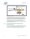
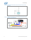
usually ensures more uniform temperatures at the fan inlet. However, additional tests
that include a solid barrier above the test motherboard surface can help evaluate the
potential impact of the chassis. This barrier is typically clear Plexiglas*, extending at
least 100 mm [4 in] in all directions beyond the edge of the thermal solution. Typical
distance from the motherboard to the barrier is 81 mm [3.2 in]. For even more
realistic airflow, the motherboard should be populated with significant elements like
memory cards, graphic card, and chipset heatsink. If a barrier is used, the
thermocouple can be taped directly to the barrier with a clear tape at the horizontal
location as previously described, half way between the fan hub and the fan housing.
If a variable speed fan is used, it may be useful to add a thermocouple taped to the
barrier above the location of the temperature sensor used by the fan to check its
speed setting against air temperature. When measuring T
A
in a chassis with a live
motherboard, add-in cards, and other system components, it is likely that the T
A