


4 Thermal and Mechanical Design Guidelines
Appendix A Heatsink Clip Load Metrology............................................................................43
A.1 Overview ............................................................................................43
A.2 Test Preparation...................................................................................43
A.2.1 Heatsink Preparation ...............................................................43
A.2.2 Typical Test Equipment ............................................................43
A.3 Test Procedure Examples.......................................................................45
Appendix B Intel
®
Enabled Boxed Processor Thermal Solution Information...............................47
Appendix C Mechanical Drawings .......................................................................................49
Figures
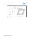
Figure 1. Micro-FCBGA Processor Package Drawing – Isometric View .....................13
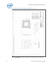
Figure 2. Micro-FCBGA Processor Package Drawing (Sheet 1 of 2).........................14
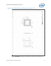
Figure 3. Micro-FCBGA Processor Package Drawing (Sheet 2 of 2).........................15
Figure 4. Vertical Lock-Down Alignment Feature.................................................18
Figure 5. Various Types of Solder Crack ...........................................................18
Figure 6. Case Study #1: Top view — Poor μATX Chassis Layout Design for
Intel
®
Celeron
®
Processor 200 Sequence on Intel
®
Desktop Board
D201GLY2 (chassis cover removed for illustration)................................
23
Figure 7. Case Study #2: Relocate System Fan to CAG Venting for Airflow
Improvement ..................................................................................
24
Figure 8. Case Study#3: An μATX Chassis Equipped with Two Exhaust Fans ...........24
Figure 9. Case Study #4: A “Top Mount Fan” PSU is located next to Processor
in μATX Chassis for System Thermal Performance Improvement .............
25
Figure 10. Processor Thermal Characterization Parameter Relationships.................29
Figure 11. Locations for Measuring Local Ambient Temperature, Active Heatsink .....31
Figure 12. Locations for Measuring Local Ambient Temperature, Passive Heatsink ...32
Figure 13. Precision Resistor Connected in-series with Processor Circuitry for
Power Measurement .........................................................................
34
Figure 14. Installation of Isotek Resistor on Intel
®
Desktop Board D201GLY2 to
Setup Connection for Power Measurement ..........................................
34
Figure 15. Probing Resistance of the Soldered Walsin Resistor (R =19.6 KΩ)
on Intel
®
Desktop Board D201GLY2 to Ensure Proper Attachment ..........35
Figure 16. Precision Resistor Soldered on on Intel
®
Desktop Board D201GLY2,
and Connected to netDAQ for Voltage Measurement.............................
35
Figure 17. Random Vibration PSD.....................................................................38
Figure 18. Shock Acceleration Curve.................................................................39
Figure 19. Top Plate and Package Simulator Fasten onto Clip Force Measurement
Machine.........................................................................................
45
Figure 20. Anchors Installed and Glued Down the BTX Base Plate – for reference only46
Figure 21. Motherboard Keep-out Footprint Definition and Height Restrictions for
Enabling Components ......................................................................
50
Figure 22. Reference Clip E21952-001 ..............................................................51
Figure 23. Reference Heatsink D96271-001 .......................................................52
Figure 24. Intel
®
Boxed Processor Thermal Solution E21953-001 ..........................53