


Mechanical Drawings
Thermal and Mechanical Design Guidelines 49
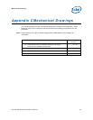
Appendix C Mechanical Drawings
The following table lists the mechanical drawings included in this appendix. These
drawings refer to the reference thermal mechanical enabling components for the
processor.
Note: Intel reserves the right to make changes and modifications to the design as
necessary.
49. Drawing Description
5
0. Page
Number
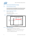
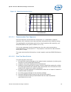
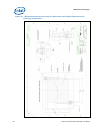
51. Motherboard Keep-out Footprint Definition and Height
Restrictions for Enabling Components
52. 50
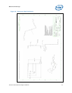
53. Reference Clip E21952-001 54. 51
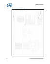
55. Reference Heatsink D96271-001 56. 52
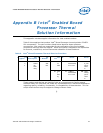
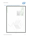
57. Intel® Boxed Processor Thermal Solution E21953-001 58. 53