Intel
®
21143 PCI/CardBus 10/100Mb/s Ethernet LAN Controller
Design Guide 17
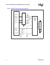
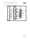
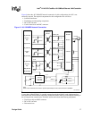
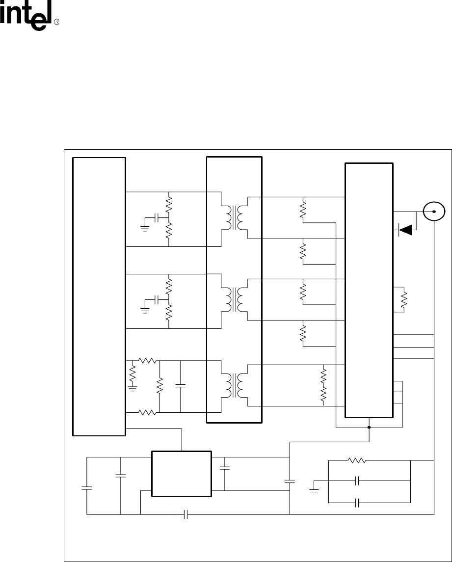
Figure 9 shows the AUI 10BASE2 network connection. In this configuration, the AUI is not
externally exposed. The required components for this configuration are as follows:
• Isolation transformer
• Terminating and decoupling components
• DC-to-DC converter
• Coaxial transceiver and BNC connector
In cases where 10BASE2 MAU is a module separate from the board, MAU can be implemented on a
small add-in card. Ensure that the cable used to connect the board to MAU provides adequate shielding of
the AUI signals from external noise. This MAU add-in card includes the following components:
• Transceiver chip and BNC connector
• DC-to-DC converter
• Discrete devices
Figure 9. AUI 10BASE2 Network Connection
LJ-05145.WMF
22 F
0.1 F
0.1 F
Isolation
Transformer
ST7032
XFMR_RD+
XFMR_RD-
XFRM_CD+
XFRM_CD-
XFMR_TD+
XFMR_TD-
Coaxial
Transceiver
NE8392
Receive
Collision
Transmit
dc-to-dc
Converter
80Z1209
0.75 pF (1000 V)
1000 pF (1000 V)
1 k
1 M
1000 pF
-9 V
Enable
+12 V
4700 pF
GND
µ
µ
µ
511
511
511
511
Coaxial
40.2
40.2
10
9
13
12
16
15
1
3
7
8
2
7
8
4
5
1
2
aui_bnc 100
Note:
Refer to the vendor data sheet for the specific implementation of the coaxial transceiver (NE8392).
GND
GND
40.2
40.2
GND
40.2
40.2
511
0.01 F µ
0.01 F µ
22 pF
47
GND
18
18
aui_rd+ 139
aui_rd- 140
aui_cd+ 137
aui_cd- 138
aui_td+ 142
aui_td- 143
21143
Transmit
Path
Receive
Path
Collision
Path
Ω
Ω
Ω
Ω
Ω
Ω
Ω
Ω
Ω
Ω
Ω
Ω
Ω
Ω
Ω
Ω


