Intel
®
21143 PCI/CardBus 10/100Mb/s Ethernet LAN Controller
Design Guide 9
3.0 Network Connection
The network connections of the 21143 can be used in 10BASE-T, AUI, MII, or SYM
configurations. Different methods are used to connect each port to the actual cable connector.
3.1 10BASE-T Twisted-Pair Network Port
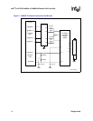
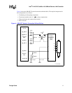
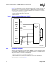
Figure 3, Figure 4, and Figure 5 show the network connection design options for 10BASE-T type
implementations.
Figure 3 and Figure 4 show two ways of connecting the 10BASE-T network by using a standard
1:1 transformer module. This implementation type requires a swing compensator (to swing the
21143 output from 3.3 V to 5 V) to meet the standard requirements.
Figure 5 shows a direct connection to a 1: transformer module. This implementation type
provides the lowest component count for 10BASE-T. The filter and transformer components
minimize any potential electromagnetic interference and radio frequency interface problems.
Common-mode noise (when noise between two lines of the same polarity add rather than cancel)
can radiate energy from the twisted-pair interface. Also, significant common-mode power supply
noise can be generated on the board or adapter by other devices. Therefore, Intel recommends the
use of filter and transformer modules that incorporate common-mode chokes.
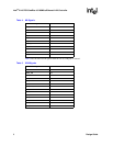
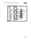
Table 8 and Table 10 list the part numbers for each implementation. Figure 3 shows the 10BASE-T
network connection with buffers. The required components for this configuration are as follows:
• Voltage swing compensator — 74ACT244
• Terminating and decoupling components
• Filter transformer and common-mode chokes
• RJ45 connector
2


