Intel
®
21143 PCI/CardBus 10/100Mb/s Ethernet LAN Controller
22 Design Guide
Intel also recommends that the connector’s shield of the adapter should be connected to the PC chassis.
5.1.1 3.3 V Power Supply
The 21143 operates with a power supply of 3.3 V. At least eight decoupling capacitors are
recommended and should contain the following values:
• Three each at 0.1 µF
• Three each at 0.01 µF
• One each at 10 µF (tantalum)
• One each at 47 µF (tantalum)
5.2 LED Status Signals
The LED connection requires a serial resistor that is connected to ground. This resistor value should
be calculated according to the type of LED used. A typical 2 mA LED requires a 750
Ω resistor. For
implementations using the boot ROM, the LED current should not exceed 2 mA. For LED indication
and programming information, refer to the CSR15 definition in the 21143 PCI /CardBus 10/100 Mb/s
Ethernet LAN Controller Hardware Reference Manual.
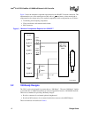
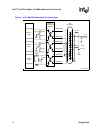
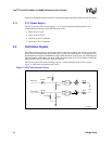
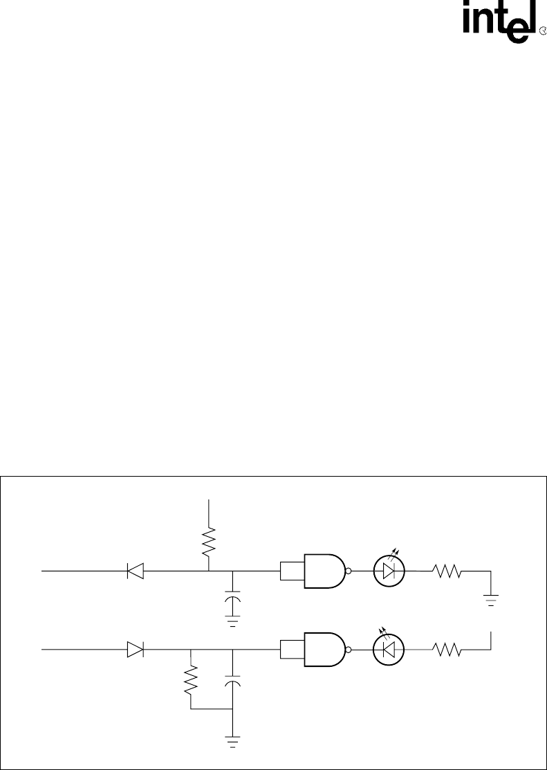
The 21143 requires LED time-stretching logic for a visible indication of the activity signal.
Figure 11 shows how to implement this circuit.
Figure 11. LED Time-Stretcher Circuit
LJ-04061.AI4
750 Ω
+5 V
22 nF
750 Ω
74
HCT132
74
HCT132
100 kΩ
22 nF
100 kΩ
+5 V
1N14B
1N14B
Active High
Active Low


