


Advanced/ZP Technical Product Summary • Page 34
Appendix I − Error messages and Beep Codes
Errors can occur during POST (Power On Self Test) which is performed every time the system is powered on. Fatal errors,
which prevent the system to continue the boot process, are communicated through a series of audible beeps. Other errors are
displayed in the following format:
ERROR Message Line 1
ERROR Message Line 2
For most displayed error messages, there is only one message. If a second message appears, it is "RUN SETUP". If this
message occurs, press <F1> to run AMIBIOS Setup.
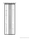
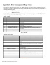
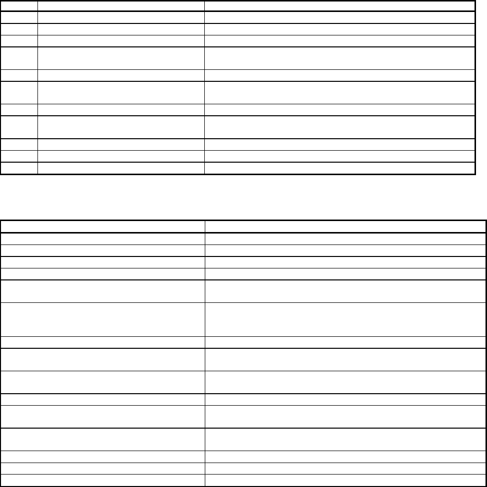
BEEP CODES
Beeps Error Message Description
1 Refresh Failure The memory refresh circuitry on the baseboard is faulty.
2 Parity Error Parity is not supported on this product, will not occur.
3 Base 64 KB Memory Failure Memory failure in the first 64 KB.
4 Timer Not Operational Memory failure in the first 64 KB of memory, or Timer 1 on the baseboard is
not functioning.
5 Processor Error The CPU on the baseboard generated an error.
6 8042 - Gate A20 Failure The keyboard controller (8042) may be bad. The BIOS cannot switch to
protected mode.
7 Processor Exception Interrupt Error The CPU generated an exception interrupt.
8 Display Memory Read/Write Error The system video adapter is either missing or its memory is faulty. This is
not a fatal error.
9 ROM Checksum Error ROM checksum value does not match the value encoded in BIOS.
10 CMOS Shutdown Register Rd/Wrt Error The shutdown register for CMOS RAM failed.
11 Cache Error / External Cache Bad The external cache is faulty.
Table I-1. Beep Codes
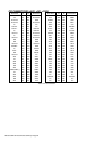
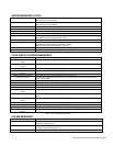
ERROR MESSAGES
Error Message Explanation
8042 Gate - A20 Error Gate A20 on the keyboard controller (8042) is not working. Replace the 8042.
Address Line Short! Error in the address decoding circuitry on the baseboard.
Cache Memory Bad, Do Not Enable Cache! Cache memory is defective. Replace it.
CH-2 Timer Error Most AT systems include two timers. There is an error in timer 2.
CMOS Battery State Low CMOS RAM is powered by a battery. The battery power is low. Replace the
battery.
CMOS Checksum Failure After CMOS RAM values are saved, a checksum value is generated for error
checking. The previous value is different from the current value. Run AMIBIOS
Setup.
CMOS System Options Not Set The values stored in CMOS RAM are either corrupt or nonexistent. Run Setup.
CMOS Display Type Mismatch The video type in CMOS RAM does not match the type detected by the BIOS.
Run AMIBIOS Setup.
CMOS Memory Size Mismatch The amount of memory on the baseboard is different than the amount in CMOS
RAM. Run AMIBIOS Setup.
CMOS Time and Date Not Set Run Standard CMOS Setup to set the date and time in CMOS RAM.
Diskette Boot Failure The boot disk in floppy drive A: is corrupt. It cannot be used to boot the system.
Use another boot disk and follow the screen instructions.
Display Switch Not Proper Some systems require a video switch on the baseboard be set to either color or
monochrome. Turn the system off, set the switch, then power on.
DMA Error Error in the DMA controller.
DMA #1 Error Error in the first DMA channel.
DMA #2 Error Error in the second DMA channel.
Table I-2. Error Messages